


One of the most important aspect of game development is creating game states which helps in different tasks like controlling game flows, managing different game windows and so on. Here in this article, we are going to show you how you can create game play systems with C++ which will help you to manage game states and empower you to control different game functionalities efficiently.
We use game states in many different ways. For example to control the game flow, handle the different ways characters can act and react, even for simple menu navigation. Needless to say, states are an important requirement for a strong and manageable code base.
There are many different types of states machines; the one we will focus in this section is the Finite State Machine (FSM) pattern. We will be creating an FSM pattern that will help you to create a more generic and flexible state machine.
This article is taken from the book Mastering C++ game Development written by Mickey Macdonald. This book shows you how you can create interesting and fun filled games with C++.
There are a few ways we can implement a simple state machine in our game. One way would be to simply use a switch case set up to control the states and an enum structure for the state types. An example of this would be as follows:
enum PlayerState
{
    Idle,
      Walking
}
...
PlayerState currentState = PlayerState::Idle; //A holder variable for the state currently in
...
// A simple function to change states
void ChangeState(PlayState nextState)
{
    currentState = nextState;
}
void Update(float deltaTime)
{
    ...
    switch(currentState)
{
    case PlayerState::Idle:
        ... //Do idle stuff
        //Change to next state
ChangeState(PlayerState::Walking);
break;
        case PlayerState::Walking:
            ... //Do walking stuff
            //Change to next state
            ChangeState(PlayerState::Idle);
break;
    }
    ...
}
Using a switch/case like this can be effective for a lot of situations, but it does have some strong drawbacks. What if we decide to add a few more states? What if we decide to add branching and more if conditionals?
The simple switch/case we started out with has suddenly become very large and undoubtedly unwieldy. Every time we want to make a change or add some functionality, we multiply the complexity and introduce more chances for bugs to creep in. We can help mitigate some of these issues and provide more flexibility by taking a slightly different approach and using classes to represent our states. Through the use of inheritance and polymorphism, we can build a structure that will allow us to chain together states and provide the flexibility to reuse them in many situations.
Let’s walk through how we can implement this in our demo examples, starting with the base class we will inherit from in the future, IState:
...
namespace BookEngine
{
    class IState {
    public:
        IState() {}
        virtual ~IState(){}
        // Called when a state enters and exits
        virtual void OnEntry() = 0;
        virtual void OnExit() = 0;

        // Called in the main game loop
        virtual void Update(float deltaTime) = 0;
    };
}
As you can see, this is just a very simple class that has a constructor, a virtual destructor, and three completely virtual functions that each inherited state must override. OnEntry, which will be called as the state is first entered, will only execute once per state change. OnExit, like OnEntry, will only be executed once per state change and is called when the state is about to be exited. The last function is the Update function; this will be called once per game loop and will contain much of the state’s logic. Although this seems very simple, it gives us a great starting point to build more complex states. Now let’s implement this basic IState class in our examples and see how we can use it for one of the common needs of a state machine: creating game states.
First, we will create a new class called GameState that will inherit from IState. This will be the new base class for all the states our game will need. The GameState.h file consists of the following:
#pragma once
#include <BookEngineIState.h>
class GameState : BookEngine::IState
{
public:
    GameState();
    ~GameState();
    //Our overrides
    virtual void OnEntry() = 0;
    virtual void OnExit() = 0;
    virtual void Update(float deltaTime) = 0;
    //Added specialty function
    virtual void Draw() = 0;
};
The GameState class is very much like the IState class it inherits from, except for one key difference. In this class, we add a new virtual method Draw() that all classes will now inherit from GameState will be implemented. Each time we use IState and create a new specialized base class, player state, menu state, and so on, we can add these new functions to customize it to the requirements of the state machine. This is how we use inheritance and polymorphism to create more complex states and state machines.
Continuing with our example, let’s now create a new GameState. We start by creating a new class called GameWaiting that inherits from GameState. To make it a little easier to follow, I have grouped all of the new GameState inherited classes into one set of files GameStates.h and GameStates.cpp. The GamStates.h file will look like the following:
#pragma once
#include "GameState.h"

class GameWaiting: GameState
{
    virtual void OnEntry() override;
    virtual void OnExit() override;
    virtual void Update(float deltaTime) override;
    virtual void Draw() override;
};

class GameRunning: GameState
{
    virtual void OnEntry() override;
    virtual void OnExit() override;
    virtual void Update(float deltaTime) override;
    virtual void Draw() override;
};

class GameOver : GameState
{
    virtual void OnEntry() override;
    virtual void OnExit() override;
    virtual void Update(float deltaTime) override;
    virtual void Draw() override;
};
Nothing new here; we are just declaring the functions for each of our GameState classes. Now, in our GameStates.cpp file, we can implement each individual state’s functions as described in the preceding code:
#include "GameStates.h"
    void GameWaiting::OnEntry()
{
...
//Called when entering the GameWaiting state's OnEntry function
...
}

void GameWaiting::OnExit()
{
...
//Called when entering the GameWaiting state's OnEntry function
...
}

void GameWaiting::Update(float deltaTime)
{
...
//Called when entering the GameWaiting state's OnEntry function
...

}

void GameWaiting::Draw()
{
...
//Called when entering the GameWaiting state's OnEntry function
...

}
...
//Other GameState implementations
...
For the sake of page space, I am only showing the GameWaiting implementation, but the same goes for the other states. Each one will have its own unique implementation of these functions, which allows you to control the code flow and implement more states as necessary without creating a hard-to-follow maze of code paths.
Now that we have our states defined, we can implement them in our game. Of course, we could go about this in many different ways. We could follow the same pattern that we did with our screen system and implement a GameState list class, a definition of which could look like the following:
    class GameState;

    class GameStateList {
    public:
        GameStateList (IGame* game);
        ~ GameStateList ();

        GameState* GoToNext();
        GameState * GoToPrevious();

        void SetCurrentState(int nextState);
        void AddState(GameState * newState);

        void Destroy();

        GameState* GetCurrent();

    protected:
        IGame* m_game = nullptr;
        std::vector< GameState*> m_states;
        int m_currentStateIndex = -1;
    };
}
Or we could simply use the GameState classes we created with a simple enum and a switch case. The use of the state pattern allows for this flexibility.
Working with cameras
At this point, we have discussed a good amount about the structure of systems and have now been able to move on to designing ways of interacting with our game and 3D environment. This brings us to an important topic: the design of virtual camera systems. A camera is what provides us with a visual representation of our 3D world. It is how we immerse ourselves and it provides us with feedback on our chosen interactions. In this section, we are going to cover the concept of a virtual camera in computer graphics.
Before we dive into writing the code for our camera, it is important to have a strong understanding of how, exactly, it all works. Let’s start with the idea of being able to navigate around the 3D world. In order to do this, we need to use what is referred to as a transformation pipeline. A transformation pipeline can be thought of as the steps that are taken to transform all objects and points relative to the position and orientation of a camera viewpoint. The following is a simple diagram that details the flow of a transformation pipeline:
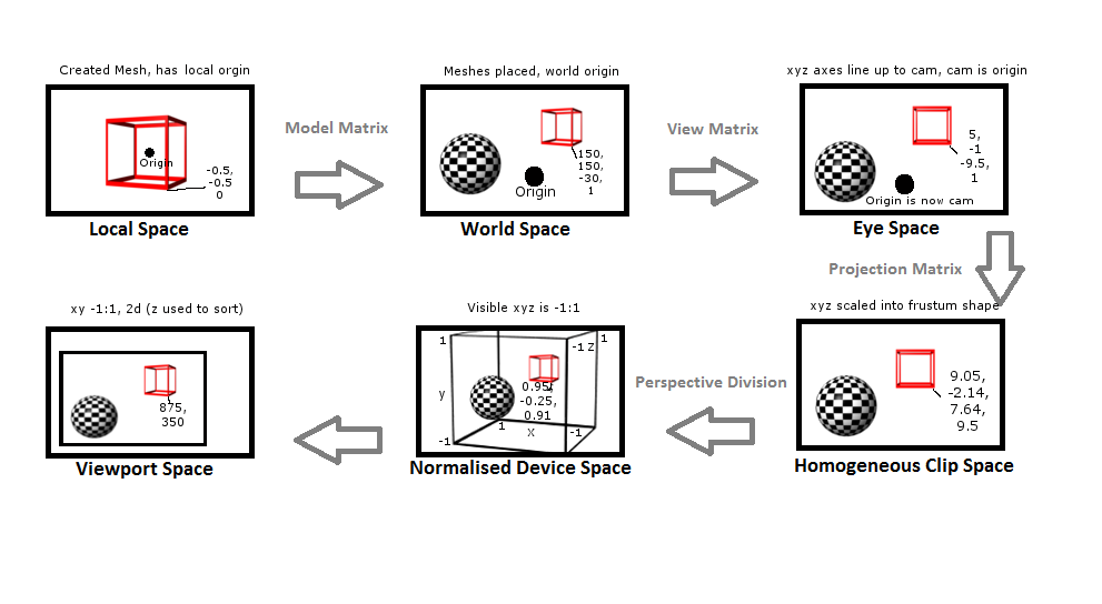 Beginning with the first step in the pipeline, local space, when a mesh is created it has a local origin 0 x, 0 y, 0 z. This local origin is typically located in either the center of the object or in the case of some player characters, the center of the feet. All points that make up that mesh are then based on that local origin. When talking about a mesh that has not been transformed, we refer to it as being in local space:
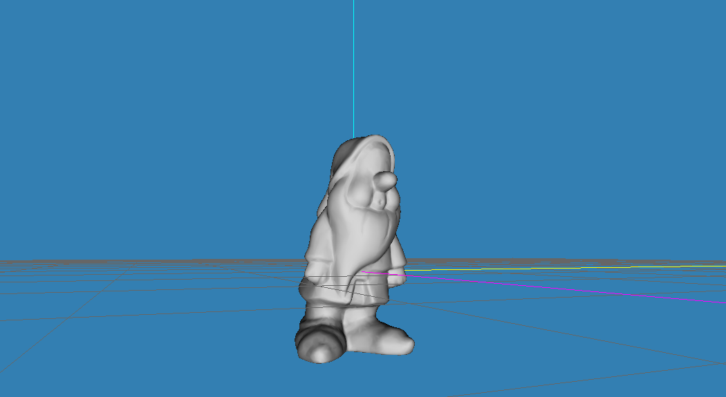
The preceding image pictures the gnome mesh in a model editor. This is what we would consider local space.
In the next step, we want to bring a mesh into our environment, the world space. In order to do this, we have to multiply our mesh points by what is referred to as a model matrix. This will then place the mesh in world space, which sets all the mesh points to be relative to a single world origin. It’s easiest to think of world space as being the description of the layout of all the objects that make up your game’s environment.
Once meshes have been placed in world space, we can start to do things such as compare distances and angles. A great example of this step is when placing game objects in a world/level editor; this is creating a description of the model’s mesh in relation to other objects and a single world origin (0,0,0). We will discuss editors in more detail in the next chapter.
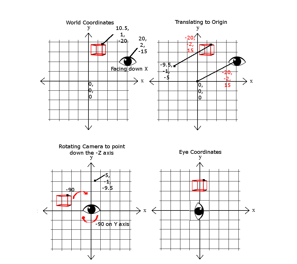
Next, in order to navigate this world space, we have to rearrange the points so that they are relative to the camera’s position and orientations. To accomplish this, we perform a few simple operations. The first is to translate the objects to the origin. First, we would move the camera from its current world coordinates.
In the following example figure, there is 20 on the x axis, 2 on the y axis, and -15 on the z axis, to the world origin or 0,0,0. We can then map the objects by subtracting the camera’s position, the values used to translate the camera object, which in this case would be -20, -2, 15. So if our game object started out at 10.5 on the x axis, 1 on the y axis, and -20 on the z axis, the newly translated coordinates would be -9.5, -1, -5.
The last operation is to rotate the camera to face the desired direction; in our current case, that would be pointing down the –z axis. For the following example, that would mean rotating the object points by -90 degrees, making the example game object’s new position 5, -1, -9.5. These operations combine into what is referred to as the view matrix:
Before we go any further, I want to briefly cover some important details when it comes to working with matrices, in particular, handling matrix multiplication and the order of operations. When working with OpenGL, all matrices are defined in a column-major layout. The opposite being row-major layout, found in other graphics libraries such as Microsoft’s DirectX. The following is the layout for column-major view matrices, where U is the unit vector pointing up, F is our vector pointing forward, R is the right vector, and P is the position of the camera:
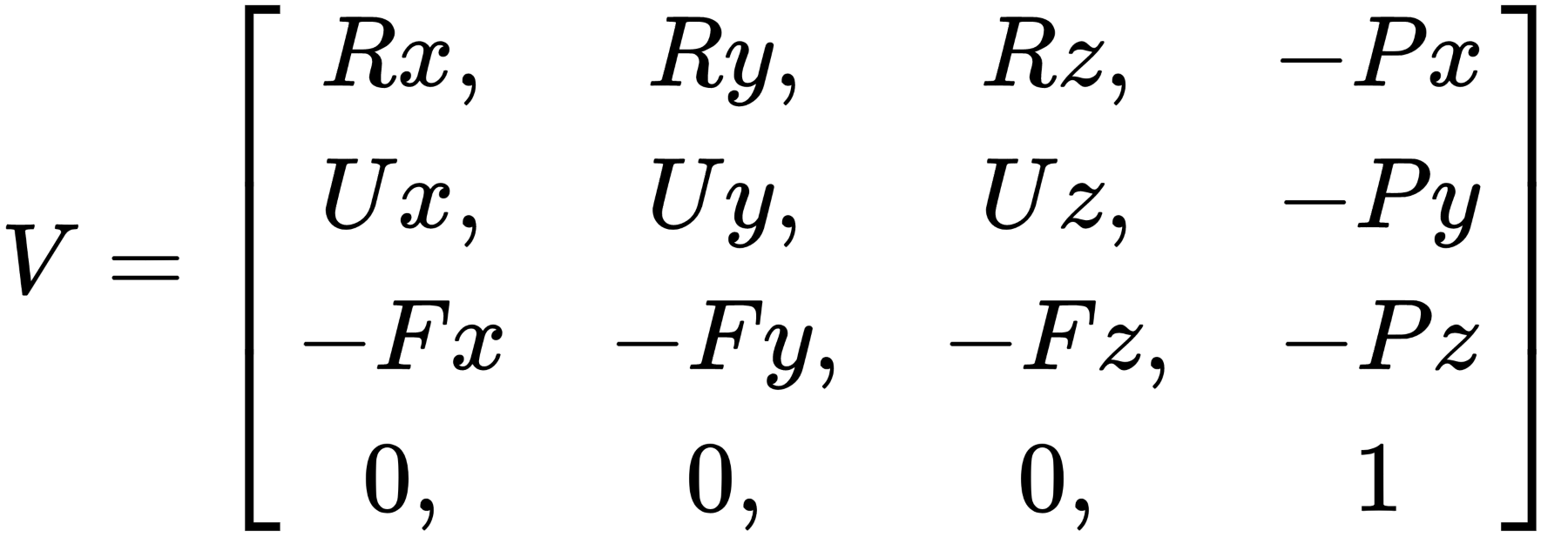
When constructing a matrix with a combination of translations and rotations, such as the preceding view matrix, you cannot, generally, just stick the rotation and translation values into a single matrix. In order to create a proper view matrix, we need to use matrix multiplication to combine two or more matrices into a single final matrix. Remembering that we are working with column-major notations, the order of the operations is therefore right to left.
This is important since, using the orientation (R) and translation (T) matrices, if we say V = T x R, this would produce an undesired effect because this would first rotate the points around the world origin and then move them to align to the camera position as the origin. What we want is V = R x T, where the points would first align to the camera as the origin and then apply the rotation. In a row-major layout, this is the other way around of course:

The good news is that we do not necessarily need to handle the creation of the view matrix manually. Older versions of OpenGL and most modern math libraries, including GLM, have an implementation of a lookAt() function. Most take a version of camera position, target or look position, and the up direction as parameters, and return a fully created view matrix. We will be looking at how to use the GLM implementation of the lookAt() function shortly, but if you want to see the full code implementation of the ideas described just now, check out the source code of GLM which is included in the project source repository.
Continuing through the transformation pipeline, the next step is to convert from eye space to homogeneous clip space. This stage will construct a projection matrix. The projection matrix is responsible for a few things.
First is to define the near and far clipping planes. This is the visible range along the defined forward axis (usually z). Anything that falls in front of the near distance and anything that falls past the far distance is considered out of range. Any geometrical objects that are on the outside of this range will be clipped (removed) from the pipeline in a later step.
Second is to define the Field of View (FOV). Despite the name, the field of view is not a field but an angle. For the FOV, we actually only specify the vertical range; most modern games use 66 or 67 degrees for this. The horizontal range will be calculated for us by the matrix once we provide the aspect ratio (how wide compared to how high). To demonstrate, a 67 degree vertical angle on a display with a 4:3 aspect ratio would have a FOV of 89.33 degrees (67 * 4/3 = 89.33).
These two steps combine to create a volume that takes the shape of a pyramid with the top chopped off. This created volume is referred to as the view frustum. Any of the geometry that falls outside of this frustum is considered to be out of view.
The following diagram illustrates what the view frustum looks like:
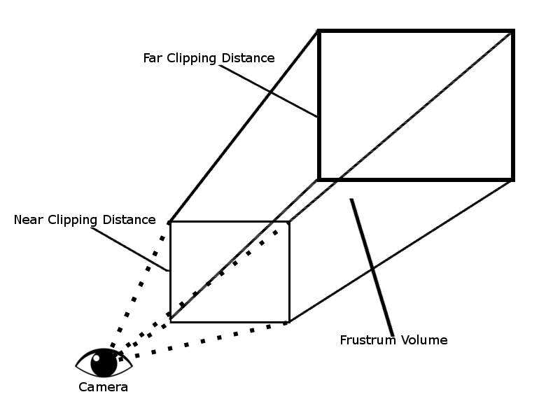
You might note that there is more visible space available at the end of the frustum than in the front. In order to properly display this on a 2D screen, we need to tell the hardware how to calculate the perspective. This is the next step in the pipeline. The larger, far end of the frustum will be pushed together creating a box shape. The collection of objects visible at this wide end will also be squeezed together; this will provide us with a perspective view. To understand this, imagine the phenomenon of looking along a straight stretch of railway tracks. As the tracks continue into the distance, they appear to get smaller and closer together.
The next step in the pipeline, after defining the clipping space, is to use what is called the perspective division to normalize the points into a box shape with the dimensions of (-1 to 1, -1 to 1, -1 to 1). This is referred to as the normalized device space. By normalizing the dimensions into unit size, we allow the points to be multiplied to scale up or down to any viewport dimensions.
The last major step in the transformation pipeline is to create the 2D representation of the 3D that will be displayed. To do this, we flatten the normalized device space with the objects further away being drawn behind the objects that are closer to the camera (draw depth). The dimensions are scaled from the X and Y normalized values into actual pixel values of the viewport. After this step, we have a 2D space referred to as the Viewport space.
That completes the transformation pipeline stages. With that theory covered, we can now shift to implementation and write some code. We are going to start by looking at the creation of a basic, first person 3D camera, which means we are looking through the eyes of the player’s character. Let’s start with the camera’s header file, Camera3D.h in the source code repository:
...
#include <glm/glm.hpp>
#include <glm/gtc/matrix_transform.hpp>
...,
We start with the necessary includes. As I just mentioned, GLM includes support for working with matrices, so we include both glm.hpp and the matrix_transform.hpp to gain access to GLM’s lookAt() function:
...
   public:
      Camera3D();
      ~Camera3D();
      void Init(glm::vec3 cameraPosition = glm::vec3(4,10,10),
              float horizontalAngle = -2.0f,
              float verticalAngle = 0.0f,
              float initialFoV = 45.0f);
      void Update();
Next, we have the public accessible functions for our Camera3D class. The first two are just the standard constructor and destructor. We then have the Init() function. We declare this function with a few defaults provided for the parameters; this way if no values are passed in, we will still have values to calculate our matrices in the first update call. That brings us to the next function declared, the Update() function. This is the function that the game engine will call each loop to keep the camera updated:
glm::mat4 GetView() { return m_view; };
glm::mat4 GetProjection() { return m_projection; };
glm::vec3 GetForward() { return m_forward; };
glm::vec3 GetRight() { return m_right; };
glm::vec3 GetUp() { return m_up; };
After the Update() function, there is a set of five getter functions to return both the View and Projection matrices, as well as the camera’s forward, up, and right vectors. To keep the implementation clean and tidy, we can simply declare and implement these getter functions right in the header file:
void SetHorizontalAngle(float angle) { m_horizontalAngle = angle; };
void SetVerticalAngle(float angle) { m_verticalAngle = angle; };
Directly after the set of getter functions, we have two setter functions. The first will set the horizontal angle, the second will set the vertical angle. This is useful for when the screen size or aspect ratio changes:
void MoveCamera(glm::vec3 movementVector) { m_position += movementVector; };
The last public function in the Camera3D class is the MoveCamera() function. This simple function takes in a vector 3, then cumulatively adds that vector to the m_position variable, which is the current camera position:
...
  private:
    glm::mat4 m_projection;
    glm::mat4 m_view; // Camera matrix
For the private declarations of the class, we start with two glm::mat4 variables. A glm::mat4 is the datatype for a 4×4 matrix. We create one for the view or camera matrix and one for the projection matrix:
glm::vec3 m_position;
float m_horizontalAngle;
float m_verticalAngle;
float m_initialFoV;
Next, we have a single vector 3 variable to hold the position of the camera, followed by three float values—one for the horizontal and one for the vertical angles, as well as a variable to hold the field of view:
glm::vec3 m_right;
glm::vec3 m_up;
glm::vec3 m_forward;
We then have three more vector 3 variable types that will hold the right, up, and forward values for the camera object.
Now that we have the declarations for our 3D camera class, the next step is to implement any of the functions that have not already been implemented in the header file. There are only two functions that we need to provide, the Init() and the Update() functions. Let’s begin with the Init() function, found in the Camera3D.cpp file:
void Camera3D::Init(glm::vec3 cameraPosition,
     float horizontalAngle,
     float verticalAngle,
     float initialFoV)
   {
     m_position = cameraPosition;
     m_horizontalAngle = horizontalAngle;
     m_verticalAngle = verticalAngle;
     m_initialFoV = initialFoV;

     Update();
    }
    ...
Our Init() function is straightforward; all we are doing in the function is taking in the provided values and setting them to the corresponding variable we declared. Once we have set these values, we simply call the Update() function to handle the calculations for the newly created camera object:
...
   void Camera3D::Update()
   {
      m_forward = glm::vec3(
          glm::cos(m_verticalAngle) * glm::sin(m_horizontalAngle),
          glm::sin(m_verticalAngle),
          glm::cos(m_verticalAngle) * glm::cos(m_horizontalAngle)
        );
The Update() function is where all of the heavy lifting of the classes is done. It starts out by calculating the new forward for our camera. This is done with a simple formula leveraging GLM’s cosine and sine functions. What is occurring is that we are converting from spherical coordinates to cartesian coordinates so that we can use the value in the creation of our view matrix.
  m_right = glm::vec3(
        glm::sin(m_horizontalAngle - 3.14f / 2.0f),
        0,
        glm::cos(m_horizontalAngle - 3.14f / 2.0f)
     );
After we calculate the new forward, we then calculate the new right vector for our camera, again using a simple formula that leverages GLM’s sine and cosine functions:
m_up = glm::cross(m_right, m_forward);
Now that we have the forward and up vectors calculated, we can use GLM’s cross-product function to calculate the new up vector for our camera. It is important that these three steps happen every time the camera changes position or rotation, and before the creation of the camera’s view matrix:
float FoV = m_initialFoV;
Next, we specify the FOV. Currently, I am just setting it back to the initial FOV specified when initializing the camera object. This would be the place to recalculate the FOV if the camera was, say, zoomed in or out (hint: mouse scroll could be useful here):
m_projection = glm::perspective(glm::radians(FoV), 4.0f / 3.0f, 0.1f, 100.0f);
Once we have the field of view specified, we can then calculate the projection matrix for our camera. Luckily for us, GLM has a very handy function called glm::perspective(), which takes in a field of view in radians, an aspect ratio, the near clipping distance, and a far clipping distance, which will then return a created projection matrix for us. Since this is an example, I have specified a 4:3 aspect ratio (4.0f/3.0f) and a clipping space of 0.1 units to 100 units directly. In production, you would ideally move these values to variables that could be changed during runtime:
 m_view = glm::lookAt(
            m_position,
            m_position + m_forward,
            m_up
         );
      }
Finally, the last thing we do in the Update() function is to create the view matrix. As I mentioned before, we are fortunate that the GLM library supplies a lookAt() function to abstract all the steps we discussed earlier in the section. This lookAt() function takes three parameters. The first is the position of the camera. The second is a vector value of where the camera is pointed, or looking at, which we provide by doing a simple addition of the camera’s current position and it’s calculated forward. The last parameter is the camera’s current up vector which, again, we calculated previously. Once finished, this function will return the newly updated view matrix to use in our graphics pipeline.
We learned to create a simple FSM game engine with C++. Checkout this book Mastering C++ game Development to learn high-end game development with advanced C++ 17 programming techniques.
Read Next:
How AI is changing game development
How to use arrays, lists, and dictionaries in Unity for 3D game development
Unity 2D & 3D game kits simplify Unity game development for beginners


")