In this article by Steven Noble, the author of the book Building Modern Networks, we will discuss networking concepts such as hyper-scale networking, software-defined networking, network hardware and software design along with a litany of network design ideas utilized in NGN.
(For more resources related to this topic, see here.)
The term Next Generation Network (NGN) has been around for over 20 years and refers to the current state of the art network equipment, protocols and features.
A big driver in NGN is the constant newer, better, faster forwarding ASICs coming out of companies like Barefoot, Broadcom, Cavium, Nephos (MediaTek) and others. The advent of commodity networking chips has shortened the development time for generic switches, allowing hyper scale networking end users to build equipment upgrades into their network designs.
At the time of writing, multiple companies have announced 6.4 Tbps switching chips. In layman terms, a 6.4 Tbps switching chip can handle 64x100GbE of evenly distributed network traffic without losing any packets. To put the number in perspective, the entire internet in 2004 was about 4 Tbps, so all of the internet traffic in 2004 could have crossed this one switching chip without issue. (Internet Traffic 1.3 EB/month http://blogs.cisco.com/sp/the-history-and-future-of-internet-traffic)
A hyper-scale network is one that is operated by companies such as Facebook, Google, Twitter and other companies that add hundreds if not thousands of new systems a month to keep up with demand.
Examples of next generation networking
At the start of the commercial internet age (1994), software routers running on minicomputers such as BBNs PDP-11 based IP routers designed in the 1970’s were still in use and hubs were simply dumb hardware devices that broadcast traffic everywhere.
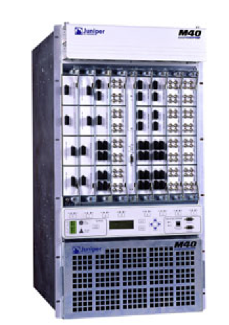
At that time, the state of the art in networking was the Cisco 7000 series router, introduced in 1993. The next generation router was the Cisco 7500 (1995), while the Cisco 12000 series (gigabit) routers and the Juniper M40 were only concepts.
When we say next generation, we are speaking of the current state of the art and the near future of networking equipment and software. For example, 100 GB Ethernet is the current state of the art, while 400 GB Ethernet is in the pipeline.
The definition of a modern network is a network that contains one or more of the following concepts:
- Software-defined Networking (SDN)
- Network design concepts
- Next generation hardware
- Hyper scale networking
- Open networking hardware and software
- Network Function Virtualization (NFV)
- Highly configurable traffic management
Both Open and Closed network hardware vendors have been innovating at a high rate of speed with the help of and due to hyper-scale companies like Google, Facebook and others who have the need for next generation high speed network devices. This provides the network architect with a reasonable pipeline of equipment to be used in designs.
Google and Facebook are both companies with hyper scale networks. A hyper scale network is one where the data stored, transferred, and updated on the network grows exponentially. Hyper scale companies deploy new equipment, software, and configurations weekly or even daily to support the needs of their customers. These companies have needs that are outside of the normal networking equipment available, so they must innovate by building their own next generation network devices, designing multi-tiered networks (like a three stage Clos network) and automating the installation and configuration of the next generation networking devices.
The need of hyper scalers is well summed up by Google’s Amin Vahdat in a 2014 Wired article “We couldn’t buy the hardware we needed to build a network of the size and speed we needed to build”.
Terms and concepts in networking
Here you will find the definition of some terms that are important in networking. They have been broken into groups of similar concepts.
Routing and switching concepts
In network devices and network designs there are many important concepts to understand. Here we begin with the way data is handled. The easiest way to discuss networking is to look at the OSI layer and point out where each device sits.
OSI Layer with respect to routers and switches:
- Layer 1 (Physical): Layer 1 includes cables, hub, and switch ports. This is how all of the devices connect to each other including copper cables (CatX), fiber optics and Direct Attach Cables (DAC) which connect SFP ports without fiber.
- Layer 2 (Data link Layer): Layer 2 includes the raw data sent over the links and manages the Media Access Control (MAC) addresses for Ethernet
- Layer 3 (Network layer): Layer 3 includes packets that have more than just layer 2 data, such as IP, IPX (Novell Networks protocol), AFP (Apple’s protocol)
Routers and switches
In a network you will have equipment that switches and/or routes traffic. A switch is a networking device that connects multiple devices such as servers, provides local connectivity and provides an uplink to the core network. A router is a network device that computes paths to remote and local devices, providing connectivity to devices across a network. Both switches and routers can use copper and fiber connections to interconnect. There are a few parts to a networking device, the forwarding chip, the TCAM, and the network processor. Some newer switches have Baseboard Management Controllers (BMCs) which manage the power, fans and other hardware, lessening the burden on the NOS to manage these devices.
Currently routers and switches are very similar as there are many Layer 3 forwarding capable switches and some Layer 2 forwarding capable routers. Making a switch Layer 3 capable is less of an issue than making a router Layer 2 forwarding as the switch already is doing Layer 2 and adding Layer 3 is not an issue. A router does not do Layer 2 forwarding in general, so it has to be modified to allow for ports to switch rather than route.
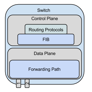
Control plane
The control plane is where all of the information about how packets should be handled is kept. Routing protocols live in the control plane and are constantly scanning information received to determine the best path for traffic to flow. This data is then packed into a simple table and pushed down to the data plane.
Data plane
The data plane is where forwarding happens. In a software router, this would be done in the devices CPU, in a hardware router, this would be done using the forwarding chip and associated memories.
VLAN/VXLAN
A Virtual Local Area Network (VLAN) is a way of creating separate logical networks within a physical network. VLANs are generally used to separate/combine different users, or network elements such as phones, servers, workstations, and so on. You can have up to 4,096 VLANs on a network segment.
A Virtual Extensible LAN (VXLAN) was created to all for large, dynamic isolated logical networks for virtualized and multiple tenant networks. You can have up to 16 million VXLANs on a network segment.
A VXLAN Tunnel Endpoint (VTEP) is a set of two logical interfaces inbound which encapsulates incoming traffic into VXLANs and outbound which removes the encapsulation of outgoing traffic from VXLAN back to its original state.
Network design concepts
Network design requires the knowledge of the physical structure of the network so that the proper design choices are made. For example, in data center you would have a local area network, if you have multiple data centers near each other, they would be considered a metro area network.
LAN
A Local Area Network (LAN), generally considered to be within the same building. These networks can be bridged (switched) or routed. In general LANs are segmented into areas to avoid large broadcast domains.
MAN
A Metro Area Network (MAN), generally defined as multiple sites in the same geographic area or city, that is, metropolitan area. A MAN generally runs at the same speed as a LAN but is able to cover larger distances.
WAN
A Wide Area Network (WAN), essentially everything that is not a LAN or MAN is a WAN. WANs generally use fiber optic cables to transmit data from one location to another. WAN circuits can be provided via multiple connections and data encapsulations including MPLS, ATM, and Ethernet.
Most large network providers utilize Dense Wavelength Division Multiplexing (DWDM) to put more bits on their fiber networks. DWDM puts multiple colors of light onto the fiber, allowing up to 128 different wavelengths to be sent down a single fiber.
DWDM has just entered open networking with the introduction of Facebook’s Voyager system.
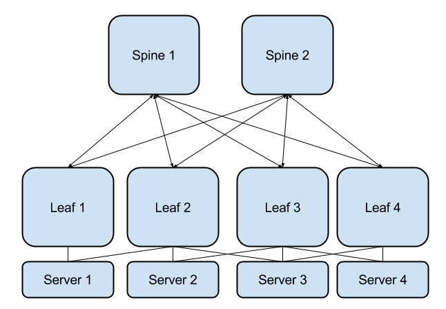
Leaf-Spine design
In a Leaf-Spine network design, there are Leaf switches (the switches that connect to the servers) sometimes called Top of Rack (ToR) switches connected to a set of Spine (switches that connect leafs together) sometimes called End of Rack (EoR) switches.
Clos network
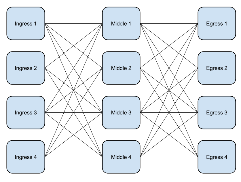
A Clos network is one of the ways to design a multi-stage network. Based on the switching network design by Charles Clos in 1952, a three stage Clos is the smallest version of a Clos network. It has an ingress, a middle, and an egress stage. Some hyper scale networks are using five stage Clos where the middle is replaced with another three stage Clos. In a five stage Clos there is an ingress, a middle ingress, a middle, a middle egress and an egress stage. All stages are connected to their neighbor, so in the example shown, Ingress 1 is connected to all four of the middle stages just as Egress 1 is connected to all four of the middle stages. A Clos network can be built in odd numbers starting with 3, so a 5, 7, and so on stage Clos is possible. For even numbered designs, Benes designs are usable.
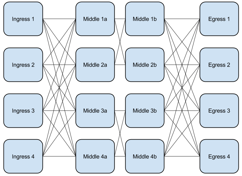
Benes network
A Benes design is a non-blocking Clos design where the middle stage is 2×2 instead of NxN. A Benes network can have even numbers of stages. Here is a four stage Benes network.
Network controller concepts
Here we will discuss the concepts of network controllers. Every networking device has a controller, whether built in or external to manage the forwarding of the system.
Controller
A controller is a computer that sits on the network and manages one or more network devices. A controller can be built into a device, like the Cisco Supervisor module or standalone like an OpenFlow controller.
The controller is responsible for managing all of the control plane data and deciding what should be sent down to the data plane.
Generally, a controller will have a Command-line Interface (CLI) and more recently a web configuration interface. Some controllers will even have an Application Programming Interface (API).
OpenFlow controller
An OpenFlow controller, as it sounds is a controller that uses the OpenFlow protocol to communicate with network devices. The most common OpenFlow controllers that people hear about are OpenDaylight and ONOS. People who are working with OpenFlow would also know of Floodlight and RYU.
Supervisor module
A route processor is a computer that sits inside of the chassis of the network device you are managing. Sometimes the route processor is built in to the system, while other times it is a module that can be replaced/upgraded. Many vendor multi-slot systems have multiple route processors for redundancy.
An example of a removable route processor is the Cisco 9500 series Supervisor module. There are multiple versions available including revision A, with a 4 core processor and 16 GB of RAM and revision B with a 6 core processor and 24 GB of RAM.
Previous systems such as the Cisco Catalyst 7600 had options such as the SUP720 (Supervisor Module 720) of which they offered multiple versions. The standard SUP720 had a limited number of routes that it could support (256k) versus the SUP720 XL which could support up to 1M routes.
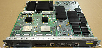
Juniper Route Engine
In Juniper terminology, the controller is called a Route Engine. They are similar to the Cisco Route Processor/Supervisor modules. Unlike Cisco Supervisor modules which utilize special CPUS, Juniper’s REs generally use common x86 CPUs. Like Cisco, Juniper multi-slot systems can have redundant processors.
Juniper has recently released the information about the NG-REs or Next Generation Route Engines. One example is the new RE-S-X6-64G, a 6-core x86 CPU based routing engine with 64 GB DRAM and 2x 64 GB SSD storage available for the MX240/MX480/MX960. These NG-REs allow for containers and other virtual machines to be run directly.
Built in processor
When looking at single rack unit (1 RU) or pizza box design switches there are some important design considerations. Most 1 RU switches do not have redundant processors, or field replaceable route processors. In general the field replaceable units (FRUs) that the customer can replace are power supplies and fans. If the failure is outside of the available FRUs, the entire switch must be replaced in the event of a failure. With white box switches this can be a simple process as white box switches can be used in multiple locations of your network including the customer edge, provider edge and core. Sparing (keeping a spare switch) is easy when you have the same hardware in multiple parts of the network.
Recently commodity switch fabric chips have come with built-in low power ARM CPUs that can be used to manage the entire system, leading to cheaper and less power hungry designs.
Facebook Wedge microserver
The Facebook Wedge is different from most white box switches as it has its controller as an add in module, the same board that is used in some of the OCP servers. By separating the controller board from the switch, different boards can be put in place, such as higher memory, faster CPUs, different CPU types, and so on.
Routing protocols
A routing protocol is a daemon that runs on a controller and communicates with other network devices to exchange route information. For this section we will use common words to demonstrate the way the routing protocol is working, these should not be construed as the actual way that the protocols talk.
BGP
Border Gateway Protocol (BGP) is a path vector based External Gateway Protocol (EGP) protocol that makes routing decisions based on paths, network policies, or rules (route-maps on Cisco). Though designed as a EGP, BGP can be used as both an interior (iboga) and exterior (eBGP) routing protocol. BGP uses keep alive packets (are you there?) to confirm that neighbors are still accessible.
BGP is the protocol that is utilized to route traffic across the internet, exchanging routing information between different Autonomous Systems (AS). An AS is all of the connected networks under the control of a single entity such as Level 3 (AS1) or Sprint (AS1239).
When two different ASes interconnect, BGP peering sessions are setup between two or more network devices that have direct connections to each other.
In an eBGP scenario, AS1 and AS1239 would setup BGP peering sessions that would allow traffic to route between their AS.
In an iBGP scenario, the same AS would peer with other routers with the same AS and transfer the routes that are defined on the system. While iBGP is used internally in most networks, iBGP is used in large corporate networks because other Interior Gateway Protocols (IGPs) may not scale.
Examples:
- iBGP next hop self
In this scenario AS1 and AS2 are peered with each other and exchanging one prefix each. AS1 advertises 192.168.1.0/24 and AS2 advertises 192.168.2.0/24. Each network has two routers, one border router, which connects to other ASes and one internal router which gets its routes from the border router. The routes are advertised internally with the next-hop set as the border router. This is a standard scenario when you are not running an IGP inside to distribute the routes for the border router external interfaces.
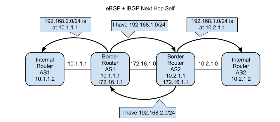
The conversation goes like this:
AS1 -> AS2: Hi AS2, I am AS1
AS2 -> AS1: Hi AS1, I am AS2
AS1 -> AS2: I have the following route, 192.168.1.0/24
AS2 – AS1: I have received the route, I have 192.168.2.0/24
AS1 – AS2: I have received the route
AS1 -> Internal Router AS1: I have this route, 192.168.2.0/24, you can reach it through me at 10.1.1.1
AS2 -> Internal Router AS2: I have this route, 192.168.1.0/24, you can reach it through me at 10.1.1.1
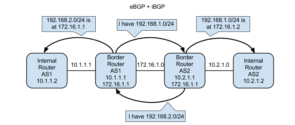
- iBGP next-hop unmodified
In the next scenario the border routers are the same, but the internal routers are given a next-hop of the external (Other AS) border router.
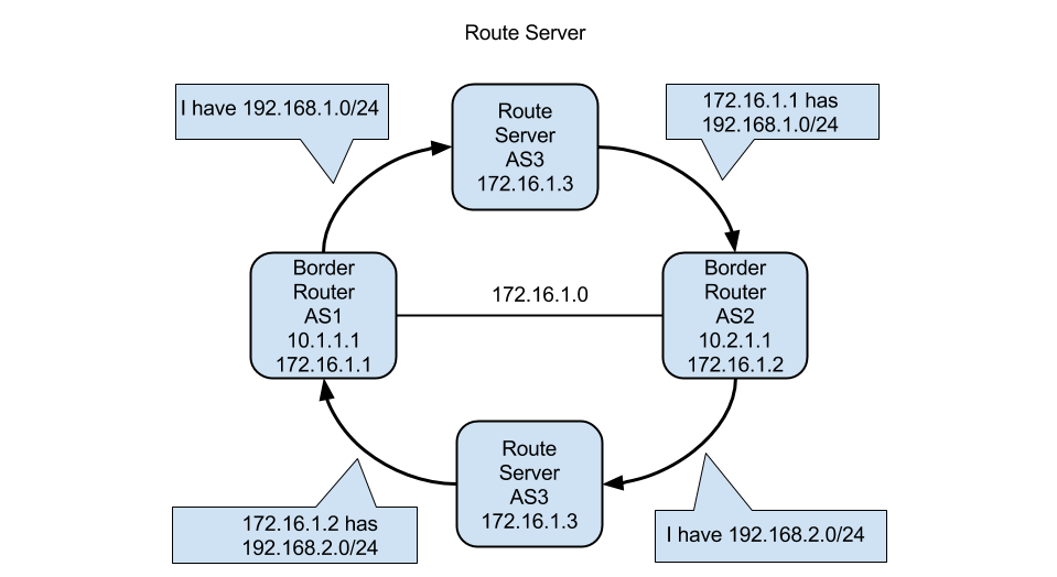
- The last scenario is where you peer with a router server, a system that handles peering, filtering the routes based on what you have specified you send. The routes are then forwarded onto your peers with your IP as the next hop.
OSPF
Open Shortest Path First (OSPF) is a relatively simple protocol. Different links on the same router are put into the same or different areas. For example, you would use area 1 for the interconnects between campuses but you would use another area, such as area 10 for the campus itself. By separating areas, you can reduce the amount of cross talk that happens between devices.
There are two versions of OSPF, v2 and v3. The main difference between v2 and v3 is that v2 is for IPv4 networks and v3 is for IPv6 networks.
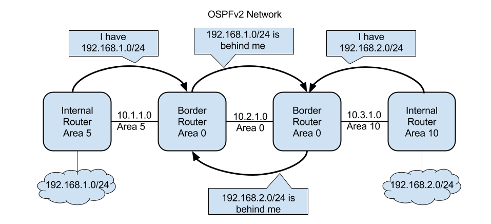
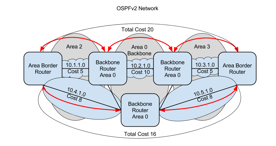
When there are multiple paths that can be taken, the cost of the links must be taken into account. Below you can see where there are two paths, one has a total cost of 20 (5+5+10), the other 16 (8+8) so the traffic will take the lowest cost link.
IS-IS
IS-IS is a link-state routing protocol, operating by flooding link state information throughout a network of routers using NETs (Network Entity Title). Each IS-IS router has its own database of the network topology, built by aggregating the flooded network information. IS-IS is used by companies who are looking for Fast convergence, scalability and Rapid flooding of new information.
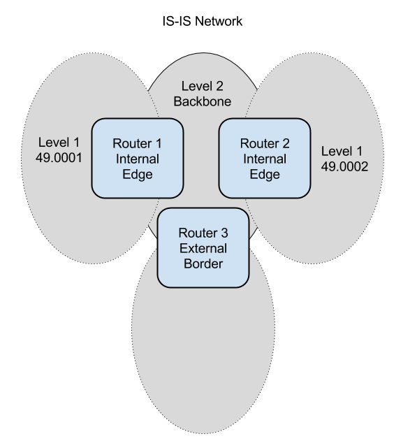
IS-IS uses the concept of levels instead of areas as in OSPF. There are two levels in IS-IS, Level 1 – area and Level2 – backbone. A Level 1 Intermediate System (IS), keeps track of the destinations within its area, while a Level 2 IS keep track of paths to the Level 1 areas.
EIGRP
Enhanced Interior Gateway Routing Protocol (EIGRP) is Cisco’s proprietary routing protocol. It is hardly ever seen in current networks but if you see it in yours, then you need to plan accordingly. Replacing EIGRP with OSPF is suggested so that you can interoperate with non-cisco devices.
RIP
If Routing Information Protocol (RIP) is being used in your network, it must be replaced during the design. Most newer routing stacks do not support RIP. RIP is one of the original routing protocols, using the number of hops (routed ports) between the device and remote location to determine the optimal path. RIP sends its entire routing database out every 30 seconds. When routing tables were small, many years ago, RIP worked fine. With larger tables, the traffic bursts and resulting re-computing by other routers in the network causes routers to run at almost 100 percent CPU all the time.
Cables
Here we will review the major types of cables.
Copper
Copper cables have been around for a very long time, originally network devices were connected together using coax cable (the same cable used for television antennas and cable). These days there are a few standard cables that are used.
- RJ45 Cables
- Cat5 – A 100Mb capable cable, used for both 10Mb and 100Mb connections
- Cat5E – 1GbE capable cable but not suggested for 1GbE networks (Cat6 is better and the price difference is nominal).
- Cat6 – A 1GbE capable cable, can be used for any speed at or below 1GbE including 100Mb and 10Mb.
- SFPs
- SFP – Small Form-factor Pluggable port. Capable of up to 1GbE connections
- SFP+ – Same size as the SFP, capable of up to 10Gb connections
- SFP28 – Same size as the SFP, capable of up to 25Gb connections
- QSFP – Quad Small Form-factor Pluggable – A bit wider than the SFP but capable of multiple GbE connections
- QSFP+ – Same size as the QSFP – capable of 40GbE as 4x10GbE on the same cable
- QSFP28 – Same size as the QSFP – capable of 100GbE
- DAC – A direct attach cable that fits into a SFP or QSFP port
Fiber/Hot pluggable
Breakout Cables
As routers and switches continue to become more dense, where the number of ports on the front of the device can no longer fit in the space, manufacturers have moved to what we call breakout cables. For example, if you have a switch that can handle 3.2Tb/s of traffic, you need to provide 3200Gbp/s of port capacity. The easiest way to do that is to use 32 100Gb ports which will fit on the front of a 1U device. You cannot fit 128 10Gb ports without using either a breakout patch panel (which will then use another few rack units (RUs), or a breakout cable.
For a period of time in the 1990’s, Cisco used RJ21 connectors to provide up to 96 ethernet ports per slot

Network engineers would then create breakout cables to go from the RJ21 to RJ45.
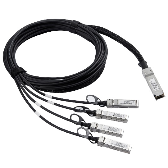
These days, we have both DAC (Direct Attach Cable) and Fiber breakout cables. For example, here you can see a 1×4 breakout cable, providing 4 10g or 25G ports from a single 40G or 100G port.
If you build a LAN network that only includes switches that provide layer 2 connectivity, any devices you want to connect together need to be in the same IP block. If you have a router in your network, it can route traffic between IP blocks.
Part 1: What defines a modern network
There is a litany of concepts that define a modern network, from simple principles to full feature sets.
In general, a next-generation data center design enables you to move to a widely distributed non-blocking fabric with uniform chipset, bandwidth, and buffering characteristics in a simple architecture.
In one example, to support these requirements, you would begin with a true three-tier Clos switching architecture with Top of Rack (ToR), spine, and fabric layers to build a data center network. Each ToR would have access to multiple fabrics and have the ability to select a desired path based on application requirement or network availability.
Following the definition of a modern network from the introduction, here we layout the general definition of the parts.
Modern network pieces
Here we will discuss the concepts that build a Next Generation Network (NGN).
Software Defined Networks
Software defined networks can be defined in multiple ways. The general definition of a Software defined network is one which can be controlled as a singular unit instead of at a system by system basis. The control-plane which would normally be in the device and using routing protocols is replaced with a controller. Software defined networks can be built using many different technologies including OpenFlow, overlay networks and automation tools.
Next generation networking and hyper scale networks
As we mention in the introduction, twenty years ago NGN hardware would have been the Cisco GSR (officially introduced in 1997) or the Juniper M40 (officially released in 1998). Large Cisco and Juniper customers would have been working with the companies to help come up with the specifications and determining how to deploy the devices (possibly Alpha or Beta versions) in their networks.
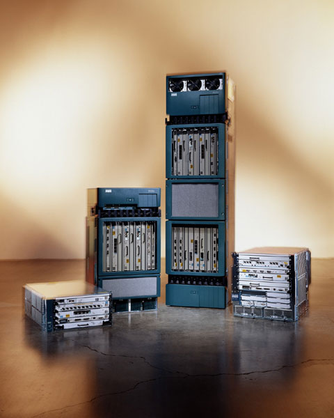
Today we can look at the hyper scale networking companies to see what a modern network looks like. A hyper scale network is one where the data stored, transferred and updated on the network grows exponentially. Technology such as 100Gb Ethernet, software defined networking, Open networking equipment and software are being deployed by hyper scale companies.
Open networking hardware overview
Open Hardware has been around for about 10 years, first in the consumer space and more recently in the enterprise space. Enterprise open networking hardware companies such as Quanta and Accton provide a significant amount of the hardware currently utilized in networks today. Companies such as Google and Facebook have been building their own hardware for many years. Facebook’s routers such as the Wedge 100 and Backpack are available publicly for end users to utilize.
Some examples of Open Networking hardware are:
- The Dell S6000-ON – a 32x40G switch with 32 QSFP ports on the front.
- The Quanta LY8 – a 48x10G + 6x40G switch with 48 SFP+ ports and 6 QSFP ports.
- The Facebook Wedge 100 – a 32x100G switch with 32 QSFP28 ports on the front.
Open networking software overview
To use open networking hardware, you need an operating system. The operating system manages the system devices such as fans, power, LEDs and temperature. On top of the operating system you will run a forwarding agent, examples of forwarding agents are Indigo, the open source OpenFlow daemon and Quagga, an open source routing agent.
Closed networking hardware overview
Cisco and Juniper are the leaders in the Closed Hardware and Software space. Cisco produces switches like the Nexus series (3000, 7000, 9000) with the 9000 programmable by ACI. Juniper provides the MX series (480, 960, 2020) with the 2020 being the highest end forwarding system they sell.
Closed networking software overview
Cisco has multiple network operating systems including IOS, NX-OS, IOS-XR. All Cisco NOSs are closed source and proprietary to the system that they run on. Cisco has what the industry calls a “industry standard CLI” which is emulated by many other companies.
Juniper ships a single NOS, JunOS which can install on multiple different systems. JunOS is a closed source BSD based NOS. The JunOS CLI is significantly different from IOS and is more focused on engineers who program.
Network Virtualization
Not to be confused with Network Function Virtualization (NFV), Network virtualization is the concept of re-creating the hardware interfaces that exist in a traditional network in software. By creating a software counterpart to the hardware interfaces, you decouple the network forwarding from the hardware.
There are a few companies and software projects that allow the end user to enable network virtualization. The first one is NSX which comes from the same team that developed OvS (Open Virtual Switch) Nicira, which was acquired by VMWare in 2012. Another project is Big Switch Networks Big Cloud Fabric, which utilizes a heavily modified version of Indigo, an OpenFlow controller.
Network Function Virtualization
Network Function Virtualization can be summed up by the statement that: “Due to recent network focused advancements in PC hardware, any service able to be delivered on proprietary, application specific hardware should be able to be done on a virtual machine”. Essentially: routers, firewalls, load balancers and other network devices all running virtualized on commodity hardware.
Traffic Engineering
Traffic engineering is a method of optimizing the performance of a telecommunications network by dynamically analyzing, predicting and regulating the behavior of data transmitted over that network.
Part 2: Next generation networking examples
In my 25 or so years of networking, I have dealt with a lot of different networking technologies, each iteration (supposedly) better than the last. Starting with Thin Net (10BASE2), moving through ArcNet, 10BASE-T, Token Ring, ATM to the Desktop, FDDI and onwards. Generally, the technology improved for each system until it was swapped out. A good example is the change from a literal ring for token ring to a switching design where devices hung off of a hub (as in 10BASE-T).
ATM to the desktop was a novel idea, providing up to 25Mbps to connected devices, but the complexity of configuring and managing it was not worth the gain.
Today almost everything is Ethernet as shown by the Facebook Voyager DWDM system, which uses Ethernet over both traditional SFP ports and the DWDM interfaces. Ethernet is simple, well supported and easy to manage.
Example 1 – Migration from FDDI to 100Base-T
In late 1996, early 1997, the Exodus network used FDDI rings (Fiber Distributed Data Interface) to connect the main routers together at 100Mbps. As the network grew we had to decide between two competing technologies, FDDI switches and Fast Ethernet (100Base-T) both providing 100Mbp/s. FDDI switches from companies like DEC (FDDI Gigaswitch) were used in most of the Internet Exchange Points (IXPs) and worked reasonably well with one minor issue, head of line blocking (HOLB), which also impacted other technologies. Head of line blocking occurs when a packet is destined for an interface that is already full, so a queue is built, if the interface continues to be full, eventually the queue will be dropped.
While we were testing the DEC FDDI Gigaswitches, we were also in deep discussions with Cisco about the availability of Fast Ethernet (FE) and working on designs. Because FE was new, there were concerns about how it would perform and how we would be able to build a redundant network design.
In the end, we decided to use FE, connect the main routers in a full mesh and use routing protocols to manage fail-over.
Example 2 – NGN Failure – LANE (LAN Emulation)
During the high growth period at Exodus communications, there was a request to connect a new data center to the original one and allow customers to put servers in both locations using the same address space. To do this, we chose LAN Emulation or LANE which allows a ATM network to be used like a LAN. On paper, LANE looked like a great idea, the ability to extend the LAN so that customers could use the same IP space in two different locations. In reality, it was very different.
For hardware, we were using Cisco 5513 switches which provided a combination of Ethernet and ATM ports.
There were multiple issues with this design:
First, the customer is provided with an ethernet interface, which runs over an ATM optical interface. Any error on the physical connection between switches or the ATM layer would cause errors on the Ethernet layer.
Second, monitoring was very hard, when there were network issues, you had to look in multiple locations to determine where the errors were happening.
After a few weeks, we did a midnight swap putting Cisco 7500 routers in to replace the 5500 switches and moving customers onto new blocks for the new data center.
Part 3: Designing a modern network
When designing a new network, some of the following might be important to you:
- Simple, focused yet non-blocking IP fabric
- Multistage parallel fabrics based on Clos network concept
- Simple merchant silicon
- Distributed control plane with some centralized controls
- Wide multi-path (ECMP)
- Uniform chipset, bandwidth, and buffering
- 1:1 oversubscribed (non-blocking fabric)
- Minimize the hardware necessary to carry east–west traffic
- Ability to support a large number of bare metal servers without adding an additional layer
- Limit fabric to a 5 stage Clos within the data center to minimize lookups and switching latency.
- Support host attachment at 10G, 25G, 50G and 100G Ethernet
- Traffic management
In a modern network one of the first decisions is whether you will use a centralized controller or not. If you use a centralized controller, you will be able to see and control the entire network from one location. If you do not use a centralized controller, you will need to either manage each system directly or via automation. There is a middle space where you can use some software defined network pieces to manage parts of the network, such as an OpenFlow controller for the WAN or VMware NSX for your virtualized workloads.
Once you know what the general management goal is, the next decision is whether to use open, proprietary, or a combination of both open and proprietary networking equipment. Open networking equipment is a concept that has been around less than a decade and started when very large network operators decided that they wanted a better control of the cost and features of the equipment in their networks. Google is a good example. In the following figure, you can see how Facebook used both their own hardware, 6-Pack/Backpack and legacy vendor hardware for their interoperability and performance testing.
Google wanted to build a high-speed backbone, but was not looking to pay the prices that the incumbent proprietary vendors such as Cisco and Juniper wanted. Google set a price per port (1G/10G/40G) that they wanted to hit and designed equipment around that. Later companies like Facebook decided to go the same direction and contracted with commodity manufacturers to build network switches that met their needs.
Proprietary vendors can offer the same level of performance or better using their massive teams of engineers to design and optimize hardware. This distinction even applies on the software side where companies like VMware and Cisco have created software defined networking tools such as NSX and ACI.
With the large amount of networking gear available, designing and building a modern network can appear to be a complex concept. Designing a modern network requires research and a good understanding of networking equipment. While complex, the task is not hard if you follow the guidelines.
These are a few of the stages of planning that need to be followed before the modern network design is started:
- The first step is to understand the scope of the project (single site, multi-site, multi-continent, multi-planet).
- The second step is to determine if the project is a green field (new) or brown field deployment (how many of the sites already exist and will/will not be upgraded).
- The third step is to determine if there will be any software defined networking (SDN), next generation networking (NGN) or Open Networking pieces.
- Finally, it is key that the equipment to be used is assembled and tested to determine if the equipment meets the needs of the network.
Summary
In this article, we have discussed many different concepts that tie NGN together. The term NGN refers to the latest and near-term networking equipment and designs. We looked at networking concepts such as local, metro and wide area networks, network controllers, routers and switches. Routing protocols such as BGP, IS-IS, OSPF and RIP.
Then we discussed many pieces that are used either singularly or together that create a modern network. In the end, we also learned some guidelines that should be followed while designing a network.
Resources for Article:
Further resources on this subject:
- Analyzing Social Networks with Facebook [article]
- Social Networks [article]
- Point-to-Point Networks [article]




![How to create sales analysis app in Qlik Sense using DAR method [Tutorial] Financial and Technical Data Analysis Graph Showing Search Findings](https://hub.packtpub.com/wp-content/uploads/2018/08/iStock-877278574-218x150.jpg)