


The OSPF interior routing protocol is a very popular protocol in enterprise networks. OSPF does a very good job in calculating cost values to choose the Shortest Path First to its destinations. OSPF operations can be separated into three categories:
- Neighbor and adjacency initialization
- LSA flooding
- SPF tree calculation
This article is an excerpt taken from the book CCNA Routing and Switching 200-125 Certification Guide by Lazaro (Laz) Diaz. This book covers the understanding of networking using routers and switches, layer 2 technology and its various configurations and connections, VLANS and inter-VLAN routing and more. In this article, we will cover the basics of OSPF, its features and configuration, and much more.
Neighbor and adjacency initialization
This is the very first part of OSPF operations. The router at this point will allocate memory for this function as well as for the maintenance of both the neighbor and topology tables. Once the router discovers which interfaces are configured with OSPF, it will begin sending hello packets throughout the interface in the hope of finding other routers using OSPF.
Let’s look at a visual representation:

Remember this would be considered a broadcast in between the routers so the election needs to run to choose DR and BDR.
00:03:06: OSPF: DR/BDR election on FastEthernet0/0
00:03:06: OSPF: Elect BDR 10.1.1.5
00:03:06: OSPF: Elect DR 10.1.1.6
00:03:06: OSPF: Elect BDR 10.1.1.5
00:03:06: OSPF: Elect DR 10.1.1.6
00:03:06: DR: 10.1.1.6 (Id) BDR: 10.1.1.5 (Id)
One thing to keep in mind is that if you are using Ethernet, as we are, the hello packet timer is set to 10 seconds. If it is not an Ethernet connection, the hello packet timer will be set to 30 seconds. Why is this so important to know? Because the hello packet timer must be identical to its adjacent router or they will never become neighbors.
Link State Advertisements and Flooding
Before we begin with LSA flooding and how it uses LSUs to create the OSPF routing table, let’s elaborate on this term.
There is not just one type of LSA either. Let’s have a look at the following table:
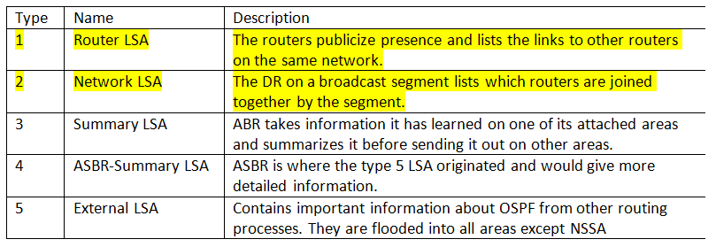
By no means are these the only LSAs that exist. There are 11 LSAs, but for the CCNA, you must know about the ones that I highlighted, do not dismiss the rest.
LSA updates are sent via multicast addresses. Depending on the type of network topology you have, that multicast address is used.
For the point-to-point networks, the multicast address is 224.0.0.5. In a broadcast environment, 224.0.0.6 is used. But as we get further into OSPF and start discussing DR/BDR routers in a broadcast environment, the DR uses 224.0.0.5 and the BDR uses 224.0.0.6. In any case, remember that these two multicast addresses are used within OSPF.
The network topology is created via LSAs updates, for which the information is acquired through LSUs or link state updates. So, OSPF routers, after they have converged, send hellos via LSAs. If any new change happens, it is the job of the LSU to update the LSA of the routers in order to keep routing tables current.
Configuring the basics of OSPF
You have already had a sneak peek into the configuration of OSPF, but let’s take it back to the basics. The following diagram shows the topology:

Yes, this is the basic topology, but we will do a dual stack, shown as follows:
Configuration of R1:

Configuration of R2:

Configuration of R3:

So, what did we do? We put the IP addresses on each interface and since we are using serial cables, on the DCE side of the cable, we must use the clock rate command and assign the clock rate for synchronization and encapsulation.
Then we configured OSPF with basic configuration, which means that all we did was advertise the networks we are attached to using the process ID number, which is local to the router. The complete network ID address we are partly using is a wildcard mask and since this is the first area, we must use area 0.
We can verify several ways to use the ping command. Use the sh ip protocols or sh ip route, but let’s look at how this would look.
Verifying from R1, you will get the following:

There are three simple commands that we could use to verify that our configuration of OSPF is correct. One thing you need to know very well is wild card masking, so let me show you a couple of examples:

Before we begin, let me you present a very simple way of doing wildcard masking. All you must do is use the constant number 255.255.255.255 and subtract your subnet mask from it:

So, as you can plainly see, your mask will determine the wildcard mask. The network ID may look the same but you will have three different wildcard masks. That would be a lot of different hosts pointing to a specific interface.
Finally, let’s look at another example, which is a subnetted Class A address:

It’s extremely simple, with no physics needed.
So, that was a basic configuration of OSPF, but you can configure OSPF in many ways. I just explained wildcard masking, but remember that zeros need to match exactly, so what can you tell me about the following configuration, using a different topology?

    R1(config)#router ospf 1
    R1(config-router)#net 0.0.0.0 0.0.0.0 area 0

    R2(config)#router ospf 2
    R2(config-router)#net 10.1.1.6 0.0.0.0 area 0
    R2(config-router)#net 10.1.1.9 0.0.0.0 area 0
    R2(config-router)#net 2.2.2.2 0.0.0.0 area 0

    R3(config)#router ospf 3
    R3(config-router)#net 10.1.1.0 0.0.0.255 area 0
    R3(config-router)#net 3.3.3.0 0.0.0.255 area 0
We configured OSPF in three different ways, so let’s explain each one.
In this new topology, we are playing around with the wildcard mask. You can see in the first configuration that when we create the network statement, we use all zeros, 0.0.0.0 0.0.0.0, and then we put in the area number.
Using all zeros means matching all interfaces, so any IP address that exists on the router will be matched by OSPF, placed in area 0, and advertised to the neighbor routers.
In the second example, when we create our network statement, we put the actual IP address of the interface and then use a wildcard mask of all zeros, 192.168.1.254 0.0.0.0. In this case, OSPF will know exactly what interface is going to participate in the OSPF process, because we are matching exactly each octet.
In the last example, the network state created was using the network ID and then we only matched the first three octets and we used 255 on the last octet, which states whatever number.
So, OSPF has tremendous flexibility in its configurations, to meet your needs on the network. You just need to know what those needs are.
By the way, I hope you spotted that I used a different process ID number on each router. Keep in mind for the CCNA and even most “real-world” networks that the process ID number is only locally significant. The other routers do not care, so this number can be whatever you want it to be.
To further prove that the three new ways of configuring OSPF work, here are the routers’ output:
    R1#sh ip route

    Gateway of last resort is not set

         1.0.0.0/32 is subnetted, 1 subnets
    C       1.1.1.1 is directly connected, Loopback1
         2.0.0.0/32 is subnetted, 1 subnets
    O       2.2.2.2 [110/2] via 10.1.1.6, 18:41:09, FastEthernet0/0
         3.0.0.0/32 is subnetted, 1 subnets
    O       3.3.3.3 [110/3] via 10.1.1.6, 18:41:09, FastEthernet0/0
         10.0.0.0/30 is subnetted, 2 subnets
    O       10.1.1.8 [110/2] via 10.1.1.6, 18:41:09, FastEthernet0/0
    C       10.1.1.4 is directly connected, FastEthernet0/0

  R1#sh ip protocols
    Routing Protocol is "ospf 1"
      Outgoing update filter list for all interfaces is not set
      Incoming update filter list for all interfaces is not set
      Router ID 1.1.1.1
      Number of areas in this router is 1. 1 normal 0 stub 0 nssa
      Maximum path: 4
      Routing for Networks:
        0.0.0.0 255.255.255.255 area 0
     Reference bandwidth unit is 100 mbps
      Routing Information Sources:
        Gateway         Distance      Last Update
        3.3.3.3              110      18:41:42
        2.2.2.2              110      18:41:42
      Distance: (default is 110)

    R1#ping 2.2.2.2

Type escape sequence to abort.
    Sending 5, 100-byte ICMP Echos to 2.2.2.2, timeout is 2 seconds:
    !!!!!
    Success rate is 100 percent (5/5), round-trip min/avg/max = 16/20/24 ms
    R1#ping 3.3.3.3

    Type escape sequence to abort.
    Sending 5, 100-byte ICMP Echos to 3.3.3.3, timeout is 2 seconds:
    !!!!!
    Success rate is 100 percent (5/5), round-trip min/avg/max = 36/52/72 ms
As you can see, I have full connectivity and by looking at my routing table, I am learning about all the routes. But I want to show the differences in the configuration of the network statements for the three routers using the sh ip protocols command:
    R2#sh ip protocols
    Routing Protocol is "ospf 2"
      Outgoing update filter list for all interfaces is not set
      Incoming update filter list for all interfaces is not set
      Router ID 2.2.2.2
      Number of areas in this router is 1. 1 normal 0 stub 0 nssa
      Maximum path: 4
      Routing for Networks:
        2.2.2.2 0.0.0.0 area 0
        10.1.1.6 0.0.0.0 area 0
        10.1.1.9 0.0.0.0 area 0
     Reference bandwidth unit is 100 mbps
      Routing Information Sources:
        Gateway         Distance      Last Update
        3.3.3.3              110      18:31:18
        1.1.1.1              110      18:31:18
      Distance: (default is 110)
    R3#sh ip protocols
    Routing Protocol is "ospf 3"
      Outgoing update filter list for all interfaces is not set
      Incoming update filter list for all interfaces is not set
      Router ID 3.3.3.3
      Number of areas in this router is 1. 1 normal 0 stub 0 nssa
      Maximum path: 4
      Routing for Networks:
        3.3.3.0 0.0.0.255 area 0
        10.1.1.0 0.0.0.255 area 0
     Reference bandwidth unit is 100 mbps
      Routing Information Sources:
        Gateway         Distance      Last Update
        2.2.2.2              110      18:47:13
        1.1.1.1              110      18:47:13
      Distance: (default is 110)
To look at other features that OSPF uses, we are going to explore the passive-interface command. This is very useful in preventing updates being sent out. But be warned, this command works differently with other routing protocols. For example, if you were to configure it on EIGRP, it will not send or receive updates. In OSPF, it simply prevents updates from being sent out, but will receive updates for neighbor routers. It will not update its routing table, so essentially that interface is down.
Let’s look from the perspective of R2:
R2(config-router)#passive-interface f1/0
*Oct  3 04:47:01.763: %OSPF-5-ADJCHG: Process 2, Nbr 1.1.1.1 on FastEthernet1/0 from FULL to DOWN, Neighbor Down: Interface down or detached
Almost immediately, it took the F1/0 interface down. What’s happening is that the router is not sending any hellos. Let’s further investigate by using the debug ip ospf hello command:
R2#debug ip ospf hello
OSPF hello events debugging is on
R2#
*Oct  3 04:49:40.319: OSPF: Rcv hello from 3.3.3.3 area 0 from FastEthernet1/1 10.1.1.10
*Oct  3 04:49:40.319: OSPF: End of hello processing
R2#
*Oct  3 04:49:43.723: OSPF: Send hello to 224.0.0.5 area 0 on FastEthernet1/1 from 10.1.1.9
R2#
*Oct  3 04:49:50.319: OSPF: Rcv hello from 3.3.3.3 area 0 from FastEthernet1/1 10.1.1.10
*Oct  3 04:49:50.323: OSPF: End of hello processing
R2#
*Oct  3 04:49:53.723: OSPF: Send hello to 224.0.0.5 area 0 on FastEthernet1/1 from 10.1.1.9
R2#
*Oct  3 04:50:00.327: OSPF: Rcv hello from 3.3.3.3 area 0 from FastEthernet1/1 10.1.1.10
*Oct  3 04:50:00.331: OSPF: End of hello processing
It is no longer sending updates out to the F1/0 interface, so let’s look at the routing table now and see what networks we know about:
    R2#sh ip route

    Gateway of last resort is not set

         2.0.0.0/32 is subnetted, 1 subnets
    C       2.2.2.2 is directly connected, Loopback2
         3.0.0.0/32 is subnetted, 1 subnets
    O       3.3.3.3 [110/2] via 10.1.1.10, 00:05:12, FastEthernet1/1
         10.0.0.0/30 is subnetted, 2 subnets
    C       10.1.1.8 is directly connected, FastEthernet1/1
    C       10.1.1.4 is directly connected, FastEthernet1/0

    R2#ping 2.2.2.2

    Type escape sequence to abort.
    Sending 5, 100-byte ICMP Echos to 2.2.2.2, timeout is 2 seconds:
    !!!!!
    Success rate is 100 percent (5/5), round-trip min/avg/max = 1/1/4 ms
    R2#ping 3.3.3.3

    Type escape sequence to abort.
    Sending 5, 100-byte ICMP Echos to 3.3.3.3, timeout is 2 seconds:
    !!!!!
    Success rate is 100 percent (5/5), round-trip min/avg/max = 20/24/40 ms
So, what are we looking at? We are only learning about the 3.3.3.3 network, which is the loopback address on R3. We have stopped learning about the 1.1.1.1 network, and we do not have connectivity to it. We can ping our own loopback, obviously, and we can ping the loopback on R3.
Okay, let’s remove the passive interface command and compare the difference:
    R2(config)#router ospf 2
    R2(config-router)#no passive-interface f1/0
    R2(config-router)#
    *Oct  3 04:57:34.343: %OSPF-5-ADJCHG: Process 2, Nbr 1.1.1.1 on FastEthernet1/0 from LOADING to FULL, Loading Done
We have now recreated our neighbor relationship with R1 once more. Let’s debug again:
R2#debug ip ospf hello
OSPF hello events debugging is on
R2#
*Oct  3 05:03:48.527: OSPF: Send hello to 224.0.0.5 area 0 on FastEthernet1/0 from 10.1.1.6
R2#
*Oct  3 05:03:50.303: OSPF: Rcv hello from 3.3.3.3 area 0 from FastEthernet1/1 10.1.1.10
*Oct  3 05:03:50.303: OSPF: End of hello processing
R2#
*Oct  3 05:03:52.143: OSPF: Rcv hello from 1.1.1.1 area 0 from FastEthernet1/0 10.1.1.5
*Oct  3 05:03:52.143: OSPF: End of hello processing
R2#
*Oct  3 05:03:53.723: OSPF: Send hello to 224.0.0.5 area 0 on FastEthernet1/1 from 10.1.1.9
Once again, we are sending and receiving hellos from R1, so let’s ping the loopback on R1, but also look at the routing table:
    R2#sh ip route

    Gateway of last resort is not set

         1.0.0.0/32 is subnetted, 1 subnets
    O 1.1.1.1 [110/2] via 10.1.1.5, 00:06:50, FastEthernet1/0
         2.0.0.0/32 is subnetted, 1 subnets
    C       2.2.2.2 is directly connected, Loopback2
         3.0.0.0/32 is subnetted, 1 subnets
    O       3.3.3.3 [110/2] via 10.1.1.10, 00:06:50, FastEthernet1/1
         10.0.0.0/30 is subnetted, 2 subnets
    C       10.1.1.8 is directly connected, FastEthernet1/1
    C       10.1.1.4 is directly connected, FastEthernet1/0

    R2#ping 1.1.1.1

    Type escape sequence to abort.
    Sending 5, 100-byte ICMP Echos to 1.1.1.1, timeout is 2 seconds:
    !!!!!
Once more, we have connectivity, so with the passive-interface be very careful how you are going to use it and which protocol you are going to use it with.
Now let’s explore another feature, which is the default-information originate. This is used in conjunction with a static-default route to create an OSPF default static route. It is like advertising a static default route. To let all the routers know if you want to get to a destination network, this is the way to go.
So, how would you configure something like that? Let’s take a look.
Use the following topology:

R1(config)# ip route 0.0.0.0 0.0.0.0 GigabitEthernet2/0

R1(config)#router ospf 1
R1(config-router)#default-information originate
Now that we have created a static route to an external network and we did the default-information originate command, what would the routing tables of the other routers look like?
R2#sh ip route
Codes: C - connected, S - static, R - RIP, M - mobile, B - BGP
       D - EIGRP, EX - EIGRP external, O - OSPF, IA - OSPF inter area
       N1 - OSPF NSSA external type 1, N2 - OSPF NSSA external type 2
       E1 - OSPF external type 1, E2 - OSPF external type 2
       i - IS-IS, su - IS-IS summary, L1 - IS-IS level-1, L2 - IS-IS level-2
       ia - IS-IS inter area, * - candidate default, U - per-user static route
       o - ODR, P - periodic downloaded static route

    Gateway of last resort is 10.1.1.5 to network 0.0.0.0

1.0.0.0/32 is subnetted, 1 subnets
O       1.1.1.1 [110/2] via 10.1.1.5, 00:16:35, FastEthernet1/0
         2.0.0.0/32 is subnetted, 1 subnets
C       2.2.2.2 is directly connected, Loopback2
         3.0.0.0/32 is subnetted, 1 subnets
O       3.3.3.3 [110/2] via 10.1.1.10, 00:16:35, FastEthernet1/1
         10.0.0.0/30 is subnetted, 2 subnets
C       10.1.1.8 is directly connected, FastEthernet1/1
C       10.1.1.4 is directly connected, FastEthernet1/0
O    192.168.1.0/24 [110/2] via 10.1.1.5, 00:16:35, FastEthernet1/0
O*E2 0.0.0.0/0 [110/1] via 10.1.1.5, 00:16:35, FastEthernet1/0

R3#sh ip route
Codes: C - connected, S - static, R - RIP, M - mobile, B - BGP
       D - EIGRP, EX - EIGRP external, O - OSPF, IA - OSPF inter area
       N1 - OSPF NSSA external type 1, N2 - OSPF NSSA external type 2
       E1 - OSPF external type 1, E2 - OSPF external type 2
       i - IS-IS, su - IS-IS summary, L1 - IS-IS level-1, L2 - IS-IS level-2
       ia - IS-IS inter area, * - candidate default, U - per-user static route
       o - ODR, P - periodic downloaded static route

Gateway of last resort is 10.1.1.9 to network 0.0.0.0

1.0.0.0/32 is subnetted, 1 subnets
O       1.1.1.1 [110/3] via 10.1.1.9, 00:17:17, FastEthernet0/0
        2.0.0.0/32 is subnetted, 1 subnets
O       2.2.2.2 [110/2] via 10.1.1.9, 00:17:17, FastEthernet0/0
         3.0.0.0/32 is subnetted, 1 subnets
C       3.3.3.3 is directly connected, Loopback3
         10.0.0.0/30 is subnetted, 2 subnets
C       10.1.1.8 is directly connected, FastEthernet0/0
O       10.1.1.4 [110/2] via 10.1.1.9, 00:17:17, FastEthernet0/0
O    192.168.1.0/24 [110/3] via 10.1.1.9, 00:17:17, FastEthernet0/0
O*E2 0.0.0.0/0 [110/1] via 10.1.1.9, 00:17:17, FastEthernet0/0

R4#sh ip route
Codes: C - connected, S - static, R - RIP, M - mobile, B - BGP
       D - EIGRP, EX - EIGRP external, O - OSPF, IA - OSPF inter area
       N1 - OSPF NSSA external type 1, N2 - OSPF NSSA external type 2
       E1 - OSPF external type 1, E2 - OSPF external type 2
       i - IS-IS, su - IS-IS summary, L1 - IS-IS level-1, L2 - IS-IS level-2
       ia - IS-IS inter area, * - candidate default, U - per-user static route
       o - ODR, P - periodic downloaded static route

Gateway of last resort is 192.168.1.1 to network 0.0.0.0

1.0.0.0/32 is subnetted, 1 subnets
D EX   1.1.1.1 [170/5376] via 192.168.1.1, 00:12:38, GigabitEthernet2/0
       2.0.0.0/32 is subnetted, 1 subnets
D EX   2.2.2.2 [170/5376] via 192.168.1.1, 00:12:38, GigabitEthernet2/0
       3.0.0.0/32 is subnetted, 1 subnets
D EX   3.3.3.3 [170/5376] via 192.168.1.1, 00:12:38, GigabitEthernet2/0
       10.0.0.0/30 is subnetted, 2 subnets
D EX  10.1.1.8 [170/5376] via 192.168.1.1, 00:12:38, GigabitEthernet2/0
D EX  10.1.1.4 [170/5376] via 192.168.1.1, 00:12:38, GigabitEthernet2/0
C    192.168.1.0/24 is directly connected, GigabitEthernet2/0
D*EX 0.0.0.0/0 [170/5376] via 192.168.1.1, 00:12:38, GigabitEthernet2/0
So, this is how you can advertise a default route to external route, using OSPF.
Obviously, you must configure EIGRP on R1 and R4 and do some redistribution. That is why all the routes are external, but you are advertising a way out using a static default route.
To summarize, this article covered OSPF configurations, features of OSPF, and different ways of advertising the networks. To know more about Multi-area OSPF configuration, check out the book CCNA Routing and Switching 200-125 Certification Guide.
Read Next
Brute forcing HTTP applications and web applications using Nmap [Tutorial]
Discovering network hosts with ‘TCP SYN’ and ‘TCP ACK’ ping scans in Nmap[Tutorial]


