


Introduction
In the middle of this year, the hacker’s watchmaker, Pebble, will launch their next products. These watches, and the non-color ones before them, are remarkably capable devices that can easily talk with other services – whether it’s to get notified of your latest mention on Twitter or get the latest weather report. Pebble have also made building applications easy by allowing you to build in JavaScript. In this post I’ll use JavaScript to show you how easy it is to build a watch application that can interact with an external service.
I could build a simple web application that gets your latest train times or Yelp reviews, but where’s the fun in that? Instead I’m going to pair a Pebble with one of the other current darlings of the hacker community, the ESP8266 WiFi module.
The ESP8266 wireless module made its entrance into the hardware community in late 2014 and things haven’t been quite the same at hacker spaces around the world. This is a device that has more memory than an Arduino, natively uses WiFi, can be programmed in C or Lua (with a custom firmware), has low power consumption and costs less than $5 per module.
It is still early days in the ESP8266 community so the edges are a bit rough, but things are stable enough to get playing and what better combination of things to play with than making some LEDs controllable wirelessly using your smart watch as an interface.
Design approach
To make the wireless LED device I’m going to use an ESP8266 with the NodeMCU firmware on it with some custom code that exposes a web server. The web server will accept a post request that has values for red, green and blue (between 0 – off, and 255 – full on, for each channel). These values will be interpreted and used to set the color of a strip of WS2812 controllable LEDs (aka NeoPixels).
Once the web service is exposed, the Pebble watch application simply needs to make an HTTP request to the ESP8266 web server, POSTing the data to it of the colour to turn the pixels.
Bill of materials
You’ll need the following to build this project
|
Qty |
Item |
Price |
Notes |
|
1 |
Pebble Watch |
$99 |
Any Pebble watch will work |
|
1 |
USB to Serial programmer |
$15 |
A 3.3 and 5v switchable USB-Serial converter is really useful. http://www.dfrobot.com/index.php?route=product/product&product_id=147 This project requires a 3.3V one |
|
1 |
ESP8266 |
$5 |
The ESP-01 is the most readily available board (even available on Amazon) http://www.amazon.com/ESP8266-ESP-01-Serial-Wireless-Transceiver/dp/B00NF0FCW8 |
|
Lots |
Jumper wires M-M, M-F |
$1 |
Get a mix |
|
1 |
2xAA battery holder |
$1 |
http://www.jameco.com/1/1/1260-bh-321-4a-r-2xaa-battery-holder-wires-mounting-tabs.html |
|
1 |
NeoPixel Strip |
$10 |
http://www.adafruit.com/neopixel |
In addition you’ll probably also want the usual hacker tools of hot glue, solder and band aids.
Prerequisites
There are a few things you’ll need to set up before you get started which will be specific to your system. This may take a little while (30-60 minutes) but the documentation linked below is exhaustive for Linux, Mac and Windows.
- Sign up for CloudPebble and get your developer account (it’s free)
- Download the Pebble SDK and install it following these directions – you need this to be able to install your JS application on your watch
- Install ESP Tool (for flashing your ESP8266 module) – this uses python so you may need a python environment if you’re using Windows.
- Install ESPlora (for uploading your application to the ESP8266 module) – this uses Java
- If you want some additional background on the ESP8266 and the development process, this excellent presentation / documentation by Andy Gelme is well worth a read.
Once your environment is ready to go, grab the files that go along with this post with the following command:
mkdir ~/watch-led
git clone https://gist.github.com/ee6fadcd837a0f46be8d.git ~/watch-led && cd ~/watch-led
Configuring the ESP8266
In order to configure the wireless module you will need to do the following things:
- Wire the module up
- Flash a binary file with the NodeMCU firmware onto the module
- Configure the application and upload that to the NodeMCU environment
- Test that the code is working
Wire the module
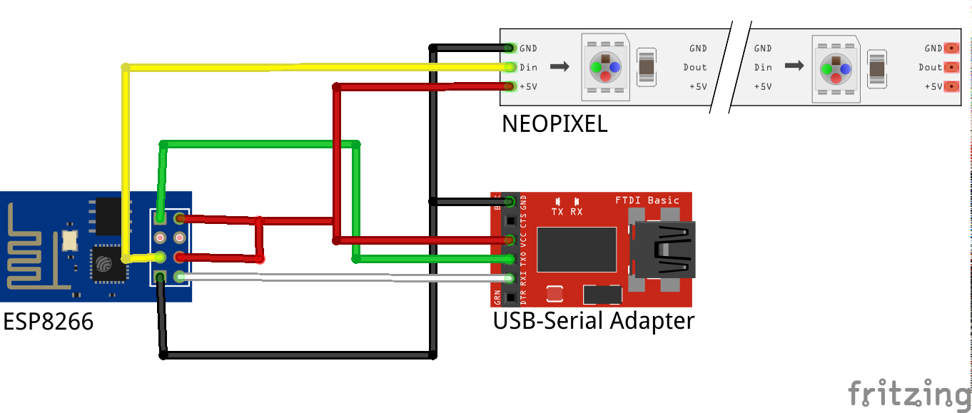
The ESP-01 module is relatively simple inasmuch as it only has 8 pins, however the use of double pin header means you can’t just plug it into a breadboard. You have a few options here, many people make a converter that uses 2×4 female header and converts this to a 1×8 strip of male header that can be plugged into a breadboard. Others (like me) make custom cables for different applications – most people just use jumper wires to join to a breadboard or other modules. You choose whatever works best for you but the wiring diagram is below.
|
ESP-01 |
USB Serial adapter |
|
1 RXD <– |
TXD |
|
2 VCC |
3.3V (make sure in range 3-3.5V) |
|
3 GPIO 0 |
Connect to ground when flashing firmware |
|
4 RESET |
3.3V resets (Don’t connect) |
|
5 GPIO 2 |
Signal line on WS2812 strip |
|
6 CH_PD |
3.3V (enables the module) |
|
7 GND |
Ground |
|
8 TXD –> |
RXD |
With the LEDs, connect VCC to 3.3V and ground to ground as well. These LEDs are happy to run off as little as 3V.
Install NodeMCU firmware
Before you install the firmware you need to put the module into “flash mode”. You do this by joining GPIO 0 (zero) to ground as you can see in the photo below illustrated by the pink wire.
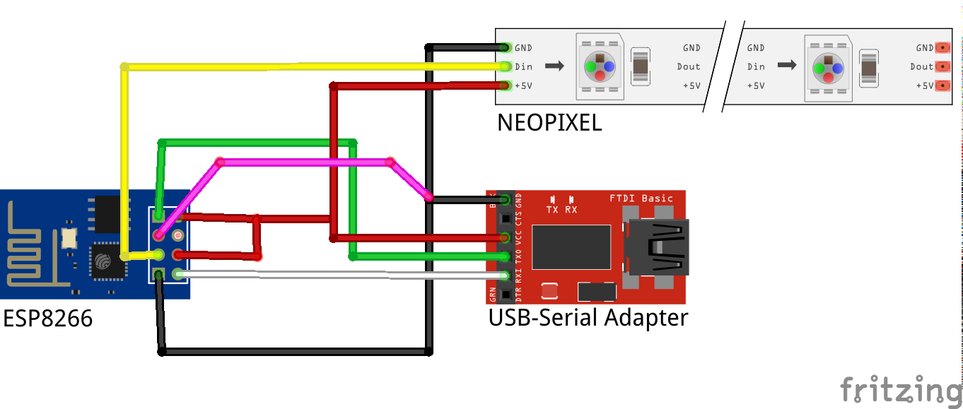
If you don’t do this, you can’t put new firmware on your module and esptool will tell you it can’t connect.
Next, issue the following commands from a terminal (assuming esptool.py is in your path):
cd ~/watch-led
esptool.py -p <<PORT>> write_flash 0x00000 nodemcu_dev_0x00000.bin 0x10000  nodemcu_dev_0x10000.bin
Note that you need to change <<PORT>> to the path to your serial port (eg /dev/ttyUSB0) – esptool will now go through the process of erasing and then flashing the NodeMCU firmware onto the module.
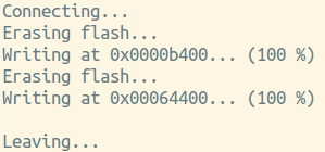
ESPtool is very simple and is fully automated
Assuming you have installed esptool and wired your module correctly you should not expect to see any errors in this process. If you do, check your wiring and your setup and then head to the GitHub repo for more information.
Once the firmware upload is complete, power down your module, remove the jumper on GPIO0 to ground and then power the module back up again.
The module is now using 9600 baud rate – if you connect using screen or minicom etc you will be dropped into a lua interpreter. Here you can issue commands and get responses.
screen /dev/ttyUSB0 9600Change /dev/ttyUSB0 for your port
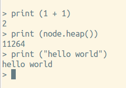
The firmware has a full lua interpreter you can play with.
Once you’ve had your fill playing with a lua interpreter, disconnect your serial connection.
Configure application
Now the module has NodeMCU on it, it’s possible to use the ESPlora IDE to talk to it, upload files to the module and write applications using Lua. Open the ESPlora IDE and connect to your module.
Select your connection from the marked area and then hit “open”.
From here, you can upload files to the module. Open up the five Lua files in the code folder you downloaded earlier. You should have setup.lua, server.lua, init.lua, config.lua and application.lua – these files can be edited directly from the code screen and then uploaded onto the ESP8266. Two files that are of interest are config and server.
Switch to the config.lua tab and update the line:
module.SSID["SSID"] = "PASSWORD"And change SSID and PASSWORD to the details for your network.
You’ll notice when you hit save (CTRL+S) that it will save and then upload the file to the module as well and confirm that is complete.
In addition you can hit the Save to ESP button which will upload it as well.
Go ahead now and upload config.lua, setup.lua, init.lua and application.lua.
Configure your LEDs
Open up the server.lua file and look for the line:
local NO_PIXELS = 17Change this to however many LEDs you have on your strip (the maximum limit is probably 50 or so before you have memory issues). There are other config options at the top of this file as well which should be fairly self explanatory.
Save this file to the module as well.
Test application is working
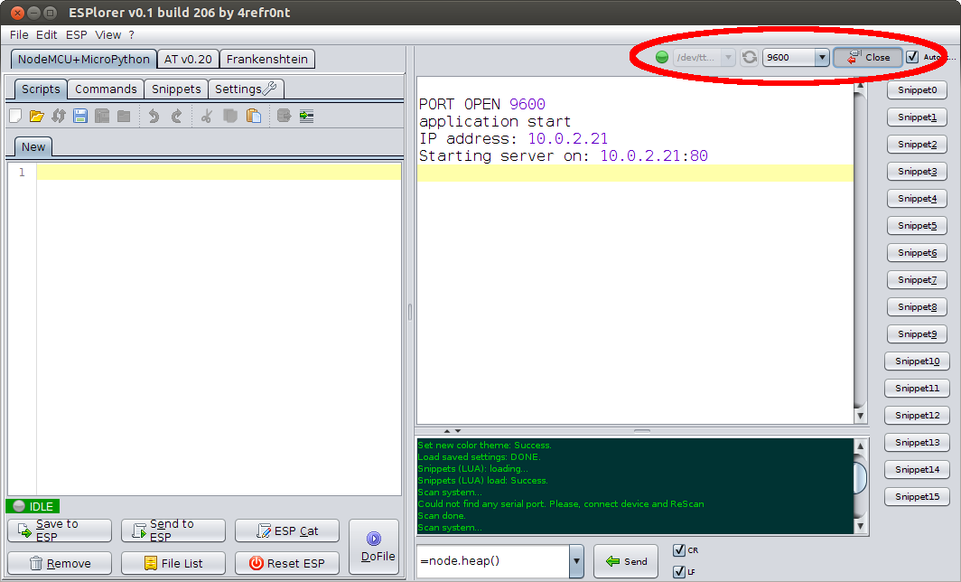
As a check before we test if the module is working properly, hit the “File List” button and you will get the files that are uploaded. Check that all five are there and if they are hit the “Reset ESP” button.
This will cause the module to restart. You’ll see a bootup sequence and after 10-15 seconds you’ll get a message showing the application has started, and the IP address of the module and the server.
You can now issue commands from curl:
curl --data "red=255&green=0&blue=255" http://<IP>Where <<IP>> is the IP address of the module.
You should at this point have some LEDs turning a nice shade of magenta. If not, backtrack a few steps and make sure each component is working – the debug log will tell you if there’s any serious issues and you can use print() statements in server.lua to print out messages. Also try things like ping IP from a command line to make sure you can see the module on your network from your computer.
Once you have your LED web service running it’s time to make it accessible from your Pebble watch.
Building the Pebble watch app
Building a Pebble watch app using a combination of the cloud pebble IDE and JavaScript makes things super easy. If you’ve done any sort of web development with JavaScript before you’ll find building apps this way really fast. Whilst the amount of access to the hardware is a bit reduced compared to C, you can make calls to external services, create interfaces and have access to the sensors so there’s plenty to play with.
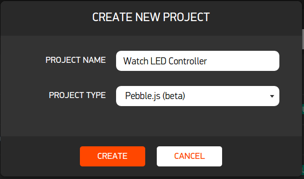
If you haven’t already, link your Pebble account to a developer account and login to CloudPebble.net – create a new project and select Pebble JS from the project type. Give your project a descriptive name.
Once created you’ll be taken to a blank workspace. Click on the app.js file under source files.

The app.js file is the main file you build your application in – you can add more but ours is really simple so we only need the one. Open up the app.js file in the repository folder on your computer and copy and paste the contents of it into the IDE.
Before you do anything else, change the HOST IP address to the IP of the ESP8266 at the top of the file. The application code is broken down with further explanations below.
var UI = require('ui');
var ajax = require('ajax');
Sets up the required UI library to draw things to the screen and gets an ajax library to make requests to web services.
function colour_request(r, g, b) {
var req = {
   url: HOST,
   method: 'post',
   data: {red:r, green:g, blue:b}
};

ajax(req,
   function(data, status, request) {
     console.log(data);
   },
   function(data, status, request) {
     console.log('The ajax request failed: ' + data + status + JSON.stringify(request));
   }
);
}
This function makes the AJAX request to our ESP8266 service posting the data. This is set up so it can be called from any interaction point within the application as we need it, taking a value for red, green and blue.
var colours = [
{ title: "OFF", r: 0, g: 0, b: 0, },
{ title: "RED", r: 255, g: 0, b: 0, },
{ title: "GREEN", r: 0, g: 255, b: 0, },
{ title: "BLUE", r: 0, g: 0, b: 255, },
{ title: "YELLOW", r: 255, g: 255, b: 0, },
{ title: "MAGENTA", r: 255, g: 0, b: 255, },
{ title: "CYAN", r: 0, g: 255, b: 255, },
{ title: "WHITE", r: 255, g: 255, b: 255, },
];
Next we define an array of objects that represent the menu items in our application. The title’s will be used for the text on the menu items and then the r,g,b values will be used in order to provide the colour values for the colour_request function.

var menu = new UI.Menu({
sections: [{
   title: 'Choose LED colour',
   items: colours
}]
});
menu.on('select', function(e) {
colour_request(e.item.r, e.item.g, e.item.b);
});

menu.show();
The last part of the code creates the UI menu items and then defines an event handler for each menu item to call the colour_request function when it is selected and then finally menu.show() puts everything in the screen.
Compile and deploy the application
When it comes time to test or deploy your application you can either download a PBW file which can then be installed on the Pebble using command line tools or else you can use the emulator that is in the IDE. To use the emulator simple save and then hit the “Play” button to run your app within a watch emulator in the IDE.
The great thing about the emulator is that you can test things like UI interactions and ensure configuration happens properly in a nice tight development loop. Unfortunately, because the emulator runs in Pebble’s network, it more than likely won’t have access to your ESP8266 which is sitting on your LAN.
One way to fix this is simply create a route through your firewall and map it to your ESP8266. I won’t get into how to do this for your particular router. Simply change the HOST IP address in the app.js file to your public Internet Address and then configure a route to your internal LAN address. If you do this you can test directly from the emulator quite happily.
The other option, and one you’ll need to do at some point anyway, is to install the application on your watch directly. Ensure your HOST IP address is updated in app.js and your phone is on the same network as the ESP8266.
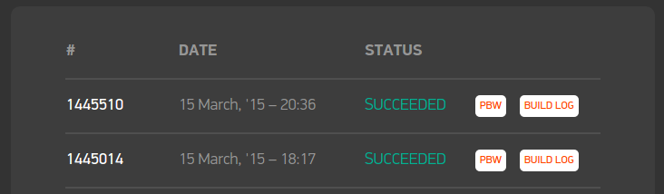
Now, from the CloudPebble IDE, click “Compilation” and then run a build. This will sit as pending for a little while and then if everything works it will go into the build log with the status “succeeded”. Download the PBW file by clicking on the “PBW” button and make note of the name of the file as it saves it to your downloads.
Open up your phone and ensure developer mode is selected as instructed in the build tools set up at the top of this post. Get the IP address from the developer connection screen, as shown below.
.png)
Open up a terminal and make sure you’ve activated the Pebble development environment. Export your phone’s IP address as shown from the developer connection tool in the Pebble app.
export PEBBLE_PHONE=<<IP ADDRESS>>Now you should be able to do things like this:
pebble pingAnd you’ll receive a notification on your watch.
If that’s the case then simply install the application with:
pebble install ~/Downloads/Watch_LED.pbwThe Pebble will vibrate when it is working.
Make it wireless
Once you have everything working, the last step is to get onto battery power. This is easy – simply remove the USB-Serial adapter then plug in the Ground and VCC of your battery pack into the ground and VCC of your setup. At that point the module will power up – wait approximately 15 seconds and you should be able to ping it (and then control the LEDs from your watch).
Going further
The Pebble Watch and the ESP8266 are both extremely interesting devices. With a small amount of JS, the watch can be connected to any service that talks standard web protocols and with only $5 and a little bit of Lua it’s possible to make a wireless hardware service that the watch can interact with. Using this basic model you can make all sorts of internet connected devices.
Here are some other things you could try now you’ve got this working:
- Extend the watch app to be able to talk to multiple ESP8266s scattered around your workspace.
- Change the event model so that the LEDs update on different notifications from your watch such as blue for a new tweet, red for a new email etc.
- Flip the service around – instead of controlling hardware, attach a sensor to the ESP8266 and then pass the data back to the watch periodically where it can display what’s happening.
About the Author
Andrew Fisher is a creator and destroyer of things that combine mobile web, ubicomp and lots of data. He is a sometime programmer, interaction researcher and CTO at JBA, a data consultancy in Melbourne, Australia. He can be found on Twitter @ajfisher.


