In this article by Salil Kapur and Nisarg Thakkar, authors of the book Mastering OpenCV Android Application Programming, we will look at the broader aspects of object tracking in Videos. Object tracking is one of the most important applications of computer vision. It can be used for many applications, some of which are as follows:
Human–computer interaction: We might want to track the position of a person's finger and use its motion to control the cursor on our machines
Surveillance: Street cameras can capture pedestrians' motions that can be tracked to detect suspicious activities
Video stabilization and compression
Statistics in sports: By tracking a player's movement in a game of football, we can provide statistics such as distance travelled, heat maps, and so on
In this article, you will learn the following topics:
Optical flow
Image Pyramids
(For more resources related to this topic, see here.)
Optical flow
Optical flow is an algorithm that detects the pattern of the motion of objects, or edges, between consecutive frames in a video. This motion may be caused by the motion of the object or the motion of the camera. Optical flow is a vector that depicts the motion of a point from the first frame to the second.
The optical flow algorithm works under two basic assumptions:
The pixel intensities are almost constant between consecutive frames
The neighboring pixels have the same motion as the anchor pixel
We can represent the intensity of a pixel in any frame by f(x,y,t). Here, the parameter t represents the frame in a video. Let's assume that, in the next dt time, the pixel moves by (dx,dy). Since we have assumed that the intensity doesn't change in consecutive frames, we can say:
f(x,y,t) = f(x + dx,y + dy,t + dt)
Now we take the Taylor series expansion of the RHS in the preceding equation:
Cancelling the common term, we get:
Where .
Dividing both sides of the equation by dt we get:
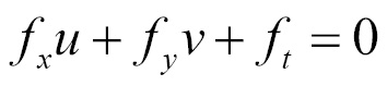
This equation is called the optical flow equation. Rearranging the equation we get:
We can see that this represents the equation of a line in the (u,v) plane. However, with only one equation available and two unknowns, this problem is under constraint at the moment.
The Horn and Schunck method
By taking into account our assumptions, we get:
We can say that the first term will be small due to our assumption that the brightness is constant between consecutive frames. So, the square of this term will be even smaller. The second term corresponds to the assumption that the neighboring pixels have similar motion to the anchor pixel. We need to minimize the preceding equation. For this, we differentiate the preceding equation with respect to u and v. We get the following equations:
Here, and are the Laplacians of u and v respectively.
The Lucas and Kanade method
We start off with the optical flow equation that we derived earlier and noticed that it is under constrained as it has one equation and two variables:
To overcome this problem, we make use of the assumption that pixels in a 3x3 neighborhood have the same optical flow:
We can rewrite these equations in the form of matrices, as shown here:
This can be rewritten in the form:
Where:
As we can see, A is a 9x2 matrix, U is a 2x1 matrix, and b is a 9x1 matrix. Ideally, to solve for U, we just need to multiply by A-1on both sides of the equation. However, this is not possible, as we can only take the inverse of square matrices. Thus, we try to transform A into a square matrix by first multiplying the equation by AT on both sides of the equation:
Now is a square matrix of dimension 2x2. Hence, we can take its inverse:
On solving this equation, we get:
This method of multiplying the transpose and then taking an inverse is called pseudo-inverse.
This equation can also be obtained by finding the minimum of the following equation:
According to the optical flow equation and our assumptions, this value should be equal to zero. Since the neighborhood pixels do not have exactly the same values as the anchor pixel, this value is very small. This method is called Least Square Error. To solve for the minimum, we differentiate this equation with respect to u and v, and equate it to zero. We get the following equations:
Now we have two equations and two variables, so this system of equations can be solved. We rewrite the preceding equations as follows:
So, by arranging these equations in the form of a matrix, we get the same equation as obtained earlier:
Since, the matrix A is now a 2x2 matrix, it is possible to take an inverse. On taking the inverse, the equation obtained is as follows:
This can be simplified as:
Solving for u and v, we get:
Now we have the values for all the , , and . Thus, we can find the values of u and v for each pixel.
When we implement this algorithm, it is observed that the optical flow is not very smooth near the edges of the objects. This is due to the brightness constraint not being satisfied. To overcome this situation, we use image pyramids.
Checking out the optical flow on Android
To see the optical flow in action on Android, we will create a grid of points over a video feed from the camera, and then the lines will be drawn for each point that will depict the motion of the point on the video, which is superimposed by the point on the grid.
Before we begin, we will set up our project to use OpenCV and obtain the feed from the camera. We will process the frames to calculate the optical flow.
First, create a new project in Android Studio. We will set the activity name to MainActivity.java and the XML resource file as activity_main.xml. Second, we will give the app the permissions to access the camera. In the AndroidManifest.xml file, add the following lines to the manifest tag:
Make sure that your activity tag for MainActivity contains the following line as an attribute:
android:screenOrientation="landscape"
Our activity_main.xml file will contain a simple JavaCameraView. This is a custom OpenCV defined layout that enables us to access the camera frames and processes them as normal Mat objects. The XML code has been shown here:
Now, let's work on some Java code. First, we'll define some global variables that we will use later in the code:
private static final String TAG = "com.packtpub.masteringopencvandroid.chapter5.MainActivity";
private static final int VIEW_MODE_KLT_TRACKER = 0;
private static final int VIEW_MODE_OPTICAL_FLOW = 1;
private int mViewMode;
private Mat mRgba;
private Mat mIntermediateMat;
private Mat mGray;
private Mat mPrevGray;
MatOfPoint2f prevFeatures, nextFeatures;
MatOfPoint features;
MatOfByte status;
MatOfFloat err;
private MenuItem mItemPreviewOpticalFlow, mItemPreviewKLT;
private CameraBridgeViewBase mOpenCvCameraView;
We will need to create a callback function for OpenCV, like we did earlier. In addition to the code we used earlier, we will also enable CameraView to capture frames for processing:
We will now check whether the OpenCV manager is installed on the phone, which contains the required libraries. In the onResume function, add the following line of code:
Notice that we called setCvCameraViewListener with the this parameter. For this, we need to make our activity implement the CvCameraViewListener2 interface. So, your class definition for the MainActivity class should look like the following code:
public class MainActivity extends Activity implements CvCameraViewListener2
We will add a menu to this activity to toggle between different examples in this article. Add the following lines to the onCreateOptionsMenu function:
We used a resetVars function to reset all the Mat objects. It has been defined as follows:
private void resetVars(){
mPrevGray = new Mat(mGray.rows(), mGray.cols(), CvType.CV_8UC1);
features = new MatOfPoint();
prevFeatures = new MatOfPoint2f();
nextFeatures = new MatOfPoint2f();
status = new MatOfByte();
err = new MatOfFloat();
}
We will also add the code to make sure that the camera is released for use by other applications, whenever our application is suspended or killed. So, add the following snippet of code to the onPause and onDestroy functions:
Unlock access to the largest independent learning library in Tech for FREE!
Get unlimited access to 7500+ expert-authored eBooks and video courses covering every tech area you can think of.
Renews at $19.99/month. Cancel anytime
if (mOpenCvCameraView != null)
mOpenCvCameraView.disableView();
After the OpenCV camera has been started, the onCameraViewStarted function is called, which is where we will add all our object initializations:
public void onCameraViewStarted(int width, int height) {
mRgba = new Mat(height, width, CvType.CV_8UC4);
mIntermediateMat = new Mat(height, width, CvType.CV_8UC4);
mGray = new Mat(height, width, CvType.CV_8UC1);
resetVars();
}
Similarly, the onCameraViewStopped function is called when we stop capturing frames. Here we will release all the objects we created when the view was started:
public void onCameraViewStopped() {
mRgba.release();
mGray.release();
mIntermediateMat.release();
}
Now we will add the implementation to process each frame of the feed that we captured from the camera. OpenCV calls the onCameraFrame method for each frame, with the frame as a parameter. We will use this to process each frame. We will use the viewMode variable to distinguish between the optical flow and the KLT tracker, and have different case constructs for the two:
public Mat onCameraFrame(CvCameraViewFrame inputFrame) {
final int viewMode = mViewMode;
switch (viewMode) {
case VIEW_MODE_OPTICAL_FLOW:
We will use the gray()function to obtain the Mat object that contains the captured frame in a grayscale format. OpenCV also provides a similar function called rgba() to obtain a colored frame. Then we will check whether this is the first run. If this is the first run, we will create and fill up a features array that stores the position of all the points in a grid, where we will compute the optical flow:
The mPrevGray object refers to the previous frame in a grayscale format. We copied the points to a prevFeatures object that we will use to calculate the optical flow and store the corresponding points in the next frame in nextFeatures. All of the computation is carried out in the calcOpticalFlowPyrLK OpenCV defined function. This function takes in the grayscale version of the previous frame, the current grayscale frame, an object that contains the feature points whose optical flow needs to be calculated, and an object that will store the position of the corresponding points in the current frame:
Now, we have the position of the grid of points and their position in the next frame as well. So, we will now draw a line that depicts the motion of each point on the grid:
List<Point> prevList=features.toList(), nextList=nextFeatures.toList();
Scalar color = new Scalar(255);
for(int i = 0; i<prevList.size(); i++){
Core.line(mGray, prevList.get(i), nextList.get(i), color);
}
Before the loop ends, we have to copy the current frame to mPrevGray so that we can calculate the optical flow in the subsequent frames:
After we end the switch case construct, we will return a Mat object. This is the image that will be displayed as an output to the user of the application. Here, since all our operations and processing were performed on the grayscale image, we will return this image:
return mGray;
So, this is all about optical flow. The result can be seen in the following image:
Optical flow at various points in the camera feed
Image pyramids
Pyramids are multiple copies of the same images that differ in their sizes. They are represented as layers, as shown in the following figure. Each level in the pyramid is obtained by reducing the rows and columns by half. Thus, effectively, we make the image's size one quarter of its original size:
Relative sizes of pyramids
Pyramids intrinsically define reduce and expand as their two operations. Reduce refers to a reduction in the image's size, whereas expand refers to an increase in its size.
We will use a convention that lower levels in a pyramid mean downsized images and higher levels mean upsized images.
Gaussian pyramids
In the reduce operation, the equation that we use to successively find levels in pyramids, while using a 5x5 sliding window, has been written as follows. Notice that the size of the image reduces to a quarter of its original size:
The elements of the weight kernel, w, should add up to 1. We use a 5x5 Gaussian kernel for this task. This operation is similar to convolution with the exception that the resulting image doesn't have the same size as the original image. The following image shows you the reduce operation:
The reduce operation
The expand operation is the reverse process of reduce. We try to generate images of a higher size from images that belong to lower layers. Thus, the resulting image is blurred and is of a lower resolution. The equation we use to perform expansion is as follows:
The weight kernel in this case, w, is the same as the one used to perform the reduce operation. The following image shows you the expand operation:
The expand operation
The weights are calculated using the Gaussian function to perform Gaussian blur.
Summary
In this article, we have seen how to detect a local and global motion in a video, and how we can track objects. We have also learned about Gaussian pyramids, and how they can be used to improve the performance of some computer vision tasks.

 United States
 Great Britain
 India
India
 Germany
 France
 Canada
 Russia
 Spain
Spain
 Brazil
 Australia
 Singapore
 Canary Islands
 Hungary
 Ukraine
 Luxembourg
 Estonia
 Lithuania
 South Korea
 Turkey
 Switzerland
 Colombia
 Taiwan
 Chile
Chile
 Norway
 Ecuador
 Indonesia
 New Zealand
 Cyprus
 Denmark
 Finland
 Poland
 Malta
Malta
 Czechia
 Austria
 Sweden
 Italy
Italy
 Egypt
Egypt
 Belgium
 Portugal
 Slovenia
 Ireland
 Romania
 Greece
 Argentina
 Netherlands
 Bulgaria
 Latvia
 South Africa
 Malaysia
 Japan
Japan
 Slovakia
 Philippines
 Mexico
 Thailand