


Laser Tanks
Recently, we had the pleasure of interviewing a group of summer intern candidates at Zappos, and we were in need of a fun and quick coding challenge. I set them each to the task of developing a robot program for RoboCode to battle it out on the virtual arena.
RoboCode is an open source programming game in which participants write a program to control an autonomous robot tank. Each tank is equipped with a cannon, a radar scanner that can detect other tanks, and wheels to move around on the arena. You write to an interface in Java or .NET, and control an event loop for default behaviors like moving around and looking for enemies, and various triggers for events like scanning another tank, getting shot or hitting a wall. This all happens in a software simulation.
The challenge turned out to be a lot of fun for the candidates as well as the spectators, but I couldn’t help but think about how much more fun it would be with real robot tanks. My hobby projects in educational robotics and irrational enthusiasm made me think that this was not only possible, but fairly easily done.
Here is a sample RoboCode program:
public class SampleRobot extends Robot {

    public void run() {
        while(true) {
            ahead(100);
            turnRight(30);
            fire(1);
            turnRight(30);
            fire(1);
            turnRight(30);
            fire(1);
        }
    }

    public void onHitByBullet(HitByBulletEvent e) {
        turnLeft(90);
        ahead(100);
    }

}
In that code, the tank goes forward for 100 units, turns 30 degrees and fires, then turns 30 degrees and fires, and turns 30 degrees one last time (for a total of 90 degrees) and fires one last time before repeating its behavior. When it is hit by a bullet it turns 90 degrees to the left and moves ahead in order to break its pattern and hopefully avoid more bullets.
In this build, we’re going to attempt to replicate this functionality in hardware. Since a single tank isn’t going to be that much fun, you might want to pull a friend or family member in to build a pair together. Let’s take a look at the parts we’ll need for this project:
|
Qty |
Item |
Source |
|
1 |
Particle Core |
https://www.Particle.io/ |
|
2 |
Continuous Rotation Servo Motors |
Pololu |
|
1 |
Photo Resistor |
Adafruit |
|
1 |
Laser Diode |
eBay |
|
2 |
10k Ohm Resistor |
Adafruit |
|
1 |
2N222A Transistor |
Adafruit |
|
1 |
Ping Pong Ball |
Anywhere |
Brains
For the brains of our laser tank, we’ll use the Particle Core, a wifi capable Arduino compatible microcontroller. It’s currently one of my favorite boards for prototyping because it comes in a breadboard friendly form factor and can be flashed wirelessly without need for a USB cable.
If you’ve never used your Particle Core before, you’ll have to register it and tell it about your WiFi internet connection. To do that, you can use their iPhone or Android app. If you are comfortable with the command line, you can also connect it via USB and use the ‘Particle-cli’ npm package to do the same thing more expediently.
You should follow the ‘getting started’ tutorial here: http://docs.Particle.io/start/ to get set up quickly. Once you’ve registered your Particle Core, you’ll be writing and uploading your code in their web based IDE.
Movement
First we’ll need a movable tank base. A two wheeled design that uses differential steering with a ball caster or skid for is popular and very easy to implement. I’ll be using a laser cut sumobot kit for our base. You can get the files to laser cut or 3D print from http://sumobotkit.com, but if you don’t have access to a 3D printer or laser cutter, you can also just use any old box and a pair of wheels that you find. A body made out of Lego® bricks would work fantastically.
Standard servo motors can only rotate between a fixed range of degrees, so make sure you have continuous rotation servo motos that can rotate well, continuously. We use continuous rotation servo motors because they are easy to control without any special motor control boards.
We’ll wire up the red (+) and black (-) wires to the 4xAA battery pack, and then run each signal wire to a PWM pin on the Particle Core. PWM stands for Pulse Width Modulation and is a method of controlling an electronic component by sending it instructions encoded as variable width pulses of electricity. Not all pins are PWM capable, but on the Particle Core, A0 and A1 are both PWM pins.
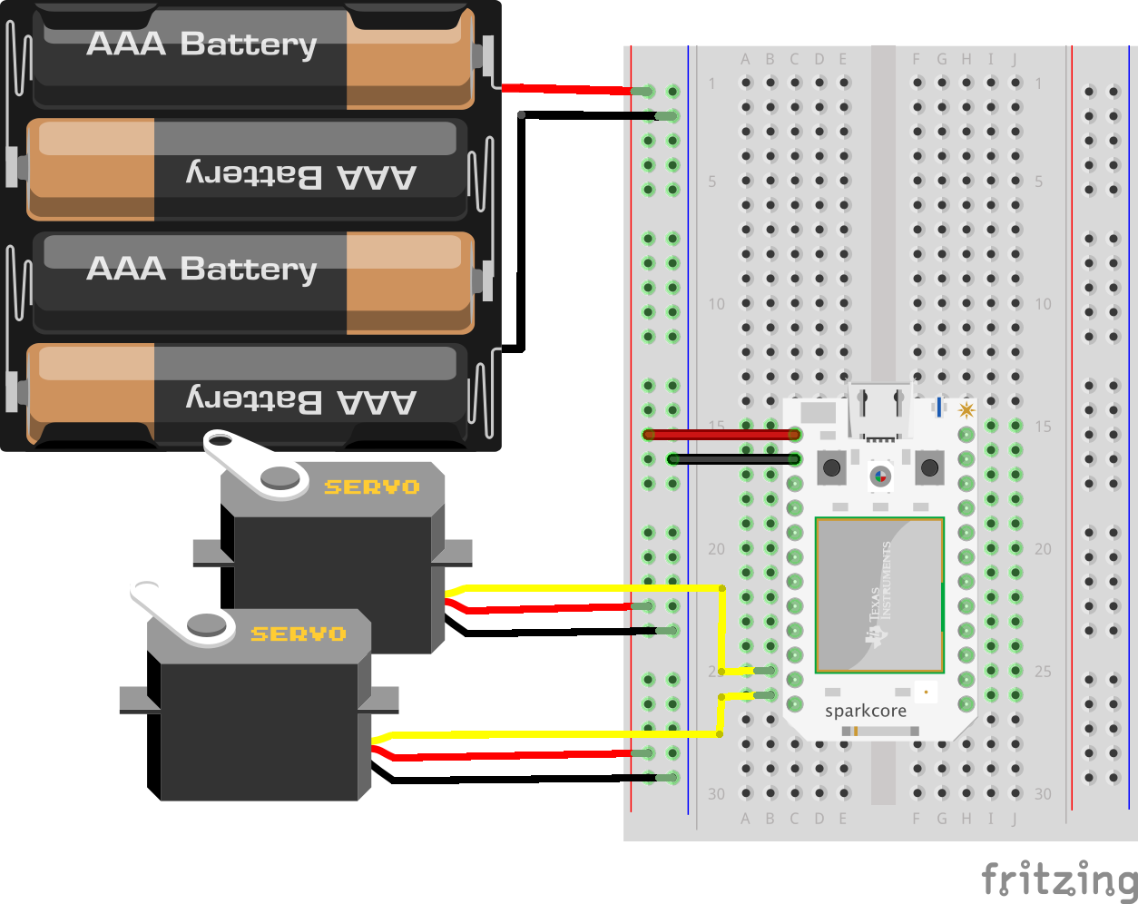
Motor Wiring
With all of our connections made, moving our tank is a simple matter. We just need to remember that since our motors are mirrored, we’ll need to move one of them clockwise and the other counter-clockwise to achieve forward motion. Reverse the directions of the motors to go in reverse, and turn them both in the same direction to turn right or left.
In normal servos, you can specify a position in degrees to move the servo to. Continuous rotation servos have the hardware to tell it when to stop removed, so they behave a little differently. 90 degrees is stopped, 0 degrees it full reverse, and 180 degrees is full speed ahead. This also works for any number in between – for example, 45 degrees is half speed reverse.
Servo left;
Servo right;

    void setup() {
    left.attach(A0);
    right.attach(A1);
    }

void ahead(int duration) {
    left.write(180);
    right.write(0);
    delay( duration * 10 );
    left.write(90);
    right.write(90);
}

void back(int duration) {
    left.write(0);
    right.write(180);
    delay( duration * 10 );
    left.write(90);
    right.write(90);
}
In RoboCode, you can specify a distance in some arbitrary unit of distance. However, we can’t accurately specify a distance to move with continuous rotation servos without installing an optical encoder that measures how fast the wheel is turning. Instead of complicating our build with an encoder, we’ll just cheat a little and make our calls time-based instead. The distance your servo will move in a given slice of time will vary with your specific model of servo motor, voltage, and wheel size, but with a little trial and error we can tune it in accurately enough. My numbers are for Spring RC SM-S4303R servos and 50mm wheels.
// How long it takes to turn 90 degrees
const int ninetyDegrees = 650;

void turnRight(int degrees) {
    left.write(180);
    right.write(180);
    delay( ( degrees / 90 ) * ninetyDegrees );
    left.write(90);
    right.write(90);
    runOnHitCode();
}

void turnLeft(int degrees) {
    left.write(0);
    right.write(0);
    delay( ( degrees / 90 ) * ninetyDegrees );
    left.write(90);
    right.write(90);
}
Shooting
Commercial Laser Tag systems use infrared beams for safety and practicality, but I personally think that using real lasers would be a lot more fun. Since our laser tank will be fairly low to the ground, under 5mw, and because I trust you not to shine the laser directly into an eyeball, I think we’re OK.
Red laser tubes are extremely inexpensive on eBay. I bought a 10 pack of 5 volt, 5 milliwatt lasers for about $5 shipped, but I’ve seen them recently for even less than that. The laser tube is pretty simple to connect: run the blue wire to ground, and the red wire to a 5 volt power source and it will fire. On a standard Arduino like the Uno R3, you could wire it up to any pin and trigger it by setting the pin to HIGH. This is also mostly true of the Particle Core, but it will be underpowered because the logic level of the Particle Core is 3.3v instead of the 5v of the Uno. Thus, we are using a transistor to boost the signal strength to 6v from the battery pack.
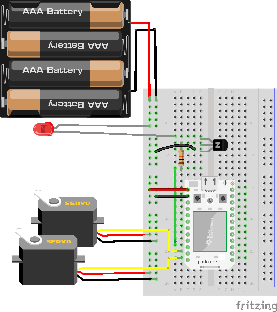
Laser Wiring
Now to shoot, we just set the pin to high for a little bit, say 500 milliseconds.
int laser = A3;

    void setup() {
        pinMode(laser, OUTPUT);
    }

void fire(int power) {
    digitalWrite(laser, HIGH);
    delay(500);
    digitalWrite(laser, LOW);
}
Getting Shot
Awesome! We now have a roving robot that can roll around and shoot at things! But how do we detect if it’s been shot? The answer is a photoresistor. A photoresistor changes resistance in relation to surrounding light levels. Unfortunately, the sensitive area of the photo resistor is just under one millimeter wide. That is a tiny target! That is why we’ll need a diffuser of some sort, and a fairly large one. If we drill a small hole in a ping-pong ball and insert the photoresistor, it will bring the ambient light level around the photoresistor down. Then, when a laser beam hits the ball, the thin shell will illuminate and the light level inside of the ball will shoot up! That is how we’ll detect a shot.
We connect the photoresistor to a 3.3v line and to ground in series with a 10k ohm resistor, acting as what we call a pull down resistor. Then we connect an analog pin (A2) between the pull down resistor and the photoresistor. If we only connected the photoresistor directly to the analog pin, the impedence would be too high and no current would flow through the photoresistor. Adding the resistor provides a path to ground the pulls the voltage down to ground and ensures there is always current flowing. The analog pin just ‘observes’ the voltage of the current flowing by like a water wheel. Without the pulldown resistor, it’s more like a wooden dam.
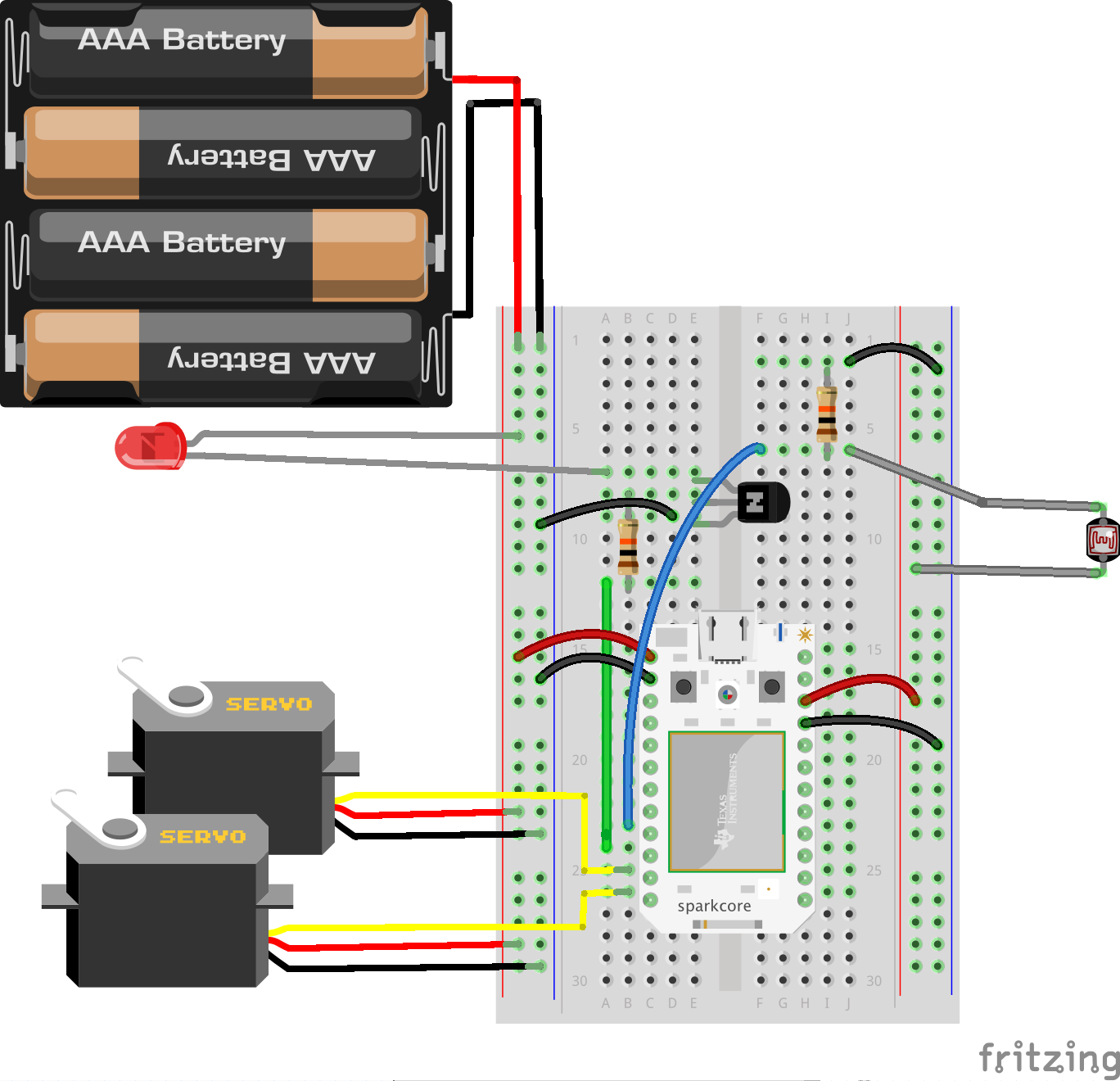
Detector Wiring
Then, we just need to watch the reading of the analog pin. If it drops below 600, that means the inside of the ball is pretty bright, and we are likely shot.
int photoCell = A2;

void setup() {
    pinMode(photoCell, INPUT);
            attachInterrupt(photoCell, checkHitStatus, CHANGE);
}

void checkHitStatus() {
lightLevel = analogRead(photoCell);
if ( lightLevel < lightThreshold ) {
    gotHit = true;
}
}
Here we have set up what’s called an interrupt. Because we are using delays for our motor movement and laser shooting, it ‘blocks’ the program or keeps it from doing anything else useful while we wait for the delay to end. If a laser were to hit our ping pong ball during a delay, we wouldn’t be able to detect it. An interrupt monitors a pin for a change and calls a function. Since this function is executed very often, we want to keep it small and fast. In our checkHitStatus function, we just get the exact reading from the pin and set a global variable signifying that we’ve been hit if it’s passed the threshold we specified.
Keeping Score
Finally, we need a way to tell how many times we’ve been hit and keep track of ‘hit points’. We can do this really simply by connecting three LEDs between pins D5, D6, D7 and ground. The LEDs will stay off by default, and then light up each time the tank is hit. When all three are lit up, we will halt the program and blink the LEDs. Game over, you lose. You can reset to the game’s beginning state by hitting the reset button on the Particle Core.
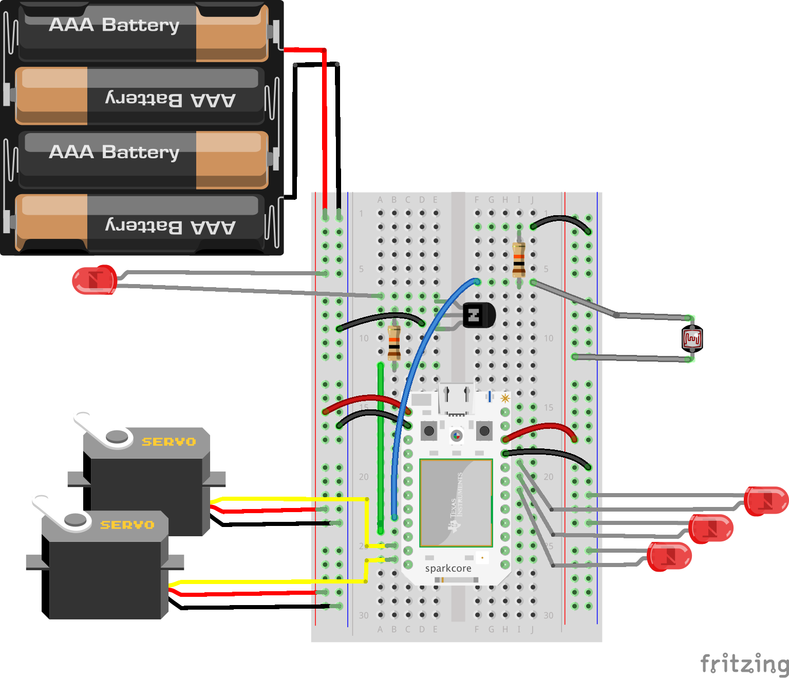
Score Wiring
int led1 = D5;
int led2 = D6;
int led3 = D7;

void setup() {
    pinMode(led1, OUTPUT);
    pinMode(led2, OUTPUT);
    pinMode(led3, OUTPUT);
}

void runOnHitCode() {
if ( gotHit ) {
    hitCount++;
    if ( hitCount == 1 ) digitalWrite(led1, HIGH);
    if ( hitCount == 2 ) digitalWrite(led2, HIGH);
    if ( hitCount == 3 ) digitalWrite(led3, HIGH);
    onHitByBullet();
    gotHit = false;
}
}
Here we are checking for the gotHit variable and returning if it’s not set. If it is set, we increase the number of times we were hit, light the appropriate LED, run the onHitByBullet() function, and reset gotHit so we can get hit again. We want to react to getting hit quickly, so we’ll run runOnHitCode() after ever action by inserting it into the ahead, fire, turnLeft and turnRight functions.
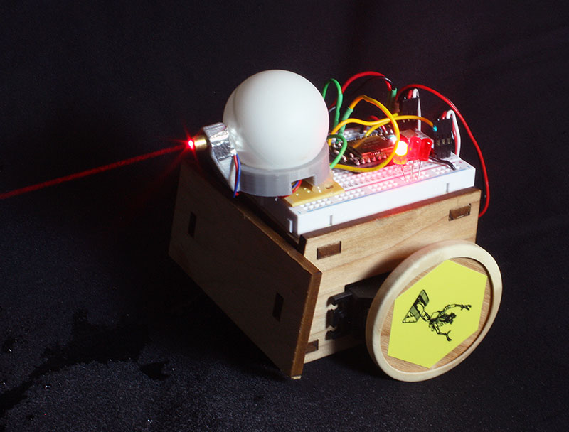
Putting Everything Together
When you are done, your board should look something like this. Note that there are some components hidden below the ping pong ball:
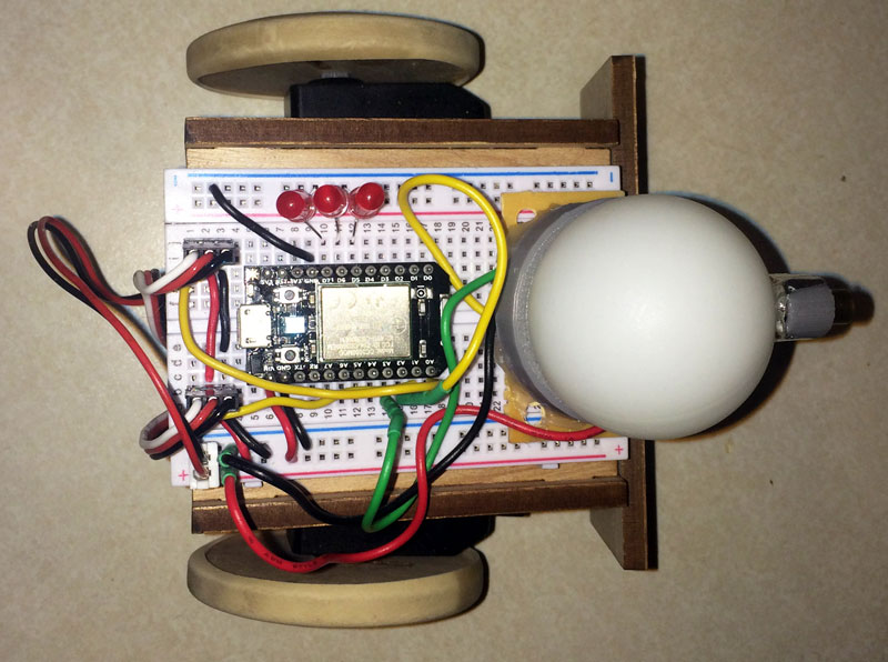
Top View
I used a 3D printed holder for the ping pong ball and laser, and you can download the STL file here. The holder isn’t necessary, as long as you mount the laser in the approximate middle of the ping pong ball and at the same height as any other tanks that you will play against. You might also want to mask out the back of your laser diode with black electrical tape so that any back reflection doesn’t accidentally trigger your own hit counter.
Let’s take a look at the combined code:
Servo left;
Servo right;
int photoCell = A2;
int laser = A3;
int led1 = D5;
int led2 = D6;
int led3 = D7;

volatile int gotHit = false;
volatile int hitCount = 0;
volatile int lightLevel = 0;

// How long it takes to turn 90 degrees
const int ninetyDegrees = 650;

// Goes lower with more light - when to trigger a 'hit'
const int lightThreshold = 1000;

void setup() {
    pinMode(photoCell, INPUT);

    attachInterrupt(photoCell, checkHitStatus, CHANGE);

    pinMode(laser, OUTPUT);

    pinMode(led1, OUTPUT);
    pinMode(led2, OUTPUT);
    pinMode(led3, OUTPUT);

    left.attach(A0);
    right.attach(A1);

            // Set a variable on the Particle API for debugging
    Particle.variable("lightLevel", &lightLevel, INT);
}

void checkHitStatus() {
    lightLevel = analogRead(photoCell);
    if ( lightLevel < lightThreshold ) {
        gotHit = true;
    }
}

void loop() {
    if ( hitCount < 3 ) {

        ahead(100);
        turnRight(30);
        fire(1);
        turnRight(30);
        fire(1);
        turnRight(30);
        fire(1);

        delay(500);
    }
}

void runOnHitCode() {
    if ( gotHit ) {
        hitCount++;
        if ( hitCount == 1 ) digitalWrite(led1, HIGH);
        if ( hitCount == 2 ) digitalWrite(led2, HIGH);
        if ( hitCount == 3 ) digitalWrite(led3, HIGH);
        onHitByBullet();
        gotHit = false;
    }
}

void ahead(int duration) {
    left.write(180);
    right.write(0);
    delay( duration * 10 );
    left.write(90);
    right.write(90);
    runOnHitCode();
}

void turnRight(int degrees) {
    left.write(180);
    right.write(180);
    delay( ( degrees / 90 ) * ninetyDegrees );
    left.write(90);
    right.write(90);
    runOnHitCode();
}

void turnLeft(int degrees) {
    left.write(0);
    right.write(0);
    delay( ( degrees / 90 ) * ninetyDegrees );
    left.write(90);
    right.write(90);
    runOnHitCode();
}

void fire(int power) {
    digitalWrite(laser, HIGH);
    delay(500);
    digitalWrite(laser, LOW);
    runOnHitCode();
}

void onHitByBullet() {
    turnLeft(90);
    ahead(100);
}
Our code has a few more extra things in it than the original RoboCode example, but the user serviceable part of the API is very similar!
Battling
There’s not much left to do but to get two tanks built and have them battle it out on a flat, smooth surface. The tanks will move around on the playing field and shoot according to the actions you and your opponent programmed in to the main run loop. When one of them hits the other, an LED will light up, and when all three are lit the opponent’s tank will stop dead.
You can vary the starting positions as the tanks will interact in different ways depending on where they started. You can and should also compete by modifying the runtime code to find the most optimal way to take out your opponent’s tank.
You don’t have to stick to a specific pattern. You can also add some entropy to make your tank move less predictably by using the rand() function like so:
// Turn randomly between 0 and 99 degrees
turnLeft( rand() % 100 );
Summary
If you’d like to have a little more fun, you can set down a few bowls of dry ice and water on the perimeter of your playing field to create a layer of fog that will make the red laser beams visible!
Of course these tanks are still shooting a little blindly. In real RoboCode, there is a scanner that is able to detect enemy tanks so as not to waste bullets. The gun can also move independently of the tank’s body on a rotatable turret and the tank can avoid obstacles. It would take another article of this size to get into the specifics of all that, but in the mean time I challenge you to think about how it might be done.
About the author
Pawel Szymczykowski is a software engineer with Zappos.com and an enthusiastic maker at his local Las Vegas hackerspace, SYN Shop. He has been programming ever since his parents bought him a Commodore 64 for Christmas. He is responsible for coming up with a simple open source design for a wooden laser cut sumo bot kit, now available at http://sumobotkit.com. As a result of the popularity of the kit, he was invited to run the robotics workshop at RobotsConf, a JSConf offshoot as well as the next JSConf (which he did attend) and Makerland Conf in his home country of Poland. He developed a healthy passion for teaching robotics through these conferences as well as local NodeBots events and programs with Code for America. He can be found on Twitter @makenai.


