


 |
A step-by-step guide to adding the 3D graphics effects used by professionals to your XNA games.
|
(For more resources on this subject, see here.)
Getting started
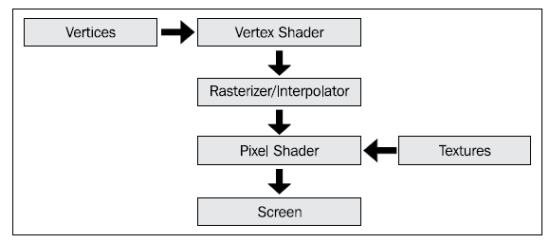
The vertex shader and pixel shader are contained in the same code file called an Effect. The vertex shader is responsible for transforming geometry from object space into screen space, usually using the world, view, and projection matrices. The pixel shader’s job is to calculate the color of every pixel onscreen. It is giving information about the geometry visible at whatever point onscreen it is being run for and takes into account lighting, texturing, and so on.
For your convenience, I’ve provided the starting code for this article here.
public class Game1 : Microsoft.Xna.Framework.Game
{
 GraphicsDeviceManager graphics;
 SpriteBatch spriteBatch;

 List<CModel> models = new List<CModel>();
 Camera camera;

 MouseState lastMouseState;

 public Game1()
 {
  graphics = new GraphicsDeviceManager(this);
  Content.RootDirectory = "Content";

  graphics.PreferredBackBufferWidth = 1280;
  graphics.PreferredBackBufferHeight = 800;
 }

// Called when the game should load its content
protected override void LoadContent()
{
 spriteBatch = new SpriteBatch(GraphicsDevice);

 models.Add(new CModel(Content.Load<Model>("ship"),
    new Vector3(0, 400, 0), Vector3.Zero, new Vector3(1f),
    GraphicsDevice));

 models.Add(new CModel(Content.Load<Model>("ground"), Vector3.Zero,
   Vector3.Zero, Vector3.One, GraphicsDevice));

 camera = new FreeCamera(new Vector3(1000, 500, -2000),
   MathHelper.ToRadians(153), // Turned around 153 degrees
   MathHelper.ToRadians(5), // Pitched up 13 degrees
   GraphicsDevice);
 lastMouseState = Mouse.GetState();
}

// Called when the game should update itself
protected override void Update(GameTime gameTime)
{
 updateCamera(gameTime);

 base.Update(gameTime);
}

void updateCamera(GameTime gameTime)
{
 // Get the new keyboard and mouse state
 MouseState mouseState = Mouse.GetState();
 KeyboardState keyState = Keyboard.GetState();

 // Determine how much the camera should turn
 float deltaX = (float)lastMouseState.X - (float)mouseState.X;
 float deltaY = (float)lastMouseState.Y - (float)mouseState.Y;

 // Rotate the camera
 ((FreeCamera)camera).Rotate(deltaX * .005f, deltaY * .005f);

 Vector3 translation = Vector3.Zero;

 // Determine in which direction to move the camera
 if (keyState.IsKeyDown(Keys.W)) translation += Vector3.Forward;
 if (keyState.IsKeyDown(Keys.S)) translation += Vector3.Backward;
 if (keyState.IsKeyDown(Keys.A)) translation += Vector3.Left;
 if (keyState.IsKeyDown(Keys.D)) translation += Vector3.Right;

 // Move 3 units per millisecond, independent of frame rate
 translation *= 4 *
 (float)gameTime.ElapsedGameTime.TotalMilliseconds;

 // Move the camera
 ((FreeCamera)camera).Move(translation);

 // Update the camera
 camera.Update();

 // Update the mouse state
 lastMouseState = mouseState;
}

// Called when the game should draw itself
protected override void Draw(GameTime gameTime)
{
  GraphicsDevice.Clear(Color.CornflowerBlue);

  foreach (CModel model in models)
  if (camera.BoundingVolumeIsInView(model.BoundingSphere))
    model.Draw(camera.View, camera.Projection,
    ((FreeCamera)camera).Position);

  base.Draw(gameTime);
 }
}
Assigning a shader to a model
In order to draw a model with XNA, it needs to have an instance of the Effect class assigned to it. Recall from the first chapter that each ModelMeshPart in a Model has its own Effect. This is because each ModelMeshPart may need to have a different appearance, as one ModelMeshPart may, for example, make up armor on a soldier while another may make up the head. If the two used the same effect (shader), then we could end up with a very shiny head or a very dull piece of armor. Instead, XNA provides us the option to give every ModelMeshPart a unique effect.
In order to draw our models with our own effects, we need to replace the BasicEffect of every ModelMeshPart with our own effect loaded from the content pipeline. For now, we won’t worry about the fact that each ModelMeshPart can have its own effect; we’ll just be assigning one effect to an entire model. Later, however, we will add more functionality to allow different effects on each part of a model.
However, before we start replacing the instances of BasicEffect assigned to our models, we need to extract some useful information from them, such as which texture and color to use for each ModelMeshPart. We will store this information in a new class that each ModelMeshPart will keep a reference to using its Tag properties:
public class MeshTag
{
  public Vector3 Color;
  public Texture2D Texture;
  public float SpecularPower;
  public Effect CachedEffect = null;

  public MeshTag(Vector3 Color, Texture2D Texture,
  float SpecularPower)
 {
  this.Color = Color;
  this.Texture = Texture;
  this.SpecularPower = SpecularPower;
 }
}
This information will be extracted using a new function in the CModel class:
private void generateTags()
{
 foreach (ModelMesh mesh in Model.Meshes)
  foreach (ModelMeshPart part in mesh.MeshParts)
   if (part.Effect is BasicEffect)
   {
    BasicEffect effect = (BasicEffect)part.Effect;
    MeshTag tag = new MeshTag(effect.DiffuseColor, effect.Texture,
      effect.SpecularPower);
    part.Tag = tag;
   }
}
This function will be called along with buildBoundingSphere() in the constructor:
...

buildBoundingSphere();
generateTags();

...
Notice that the MeshTag class has a CachedEffect variable that is not currently used. We will use this value as a location to store a reference to an effect that we want to be able to restore to the ModelMeshPart on demand. This is useful when we want to draw a model using a different effect temporarily without having to completely reload the model’s effects afterwards. The functions that will allow us to do this are as shown:
// Store references to all of the model's current effects
public void CacheEffects()
{
 foreach (ModelMesh mesh in Model.Meshes)
  foreach (ModelMeshPart part in mesh.MeshParts)
    ((MeshTag)part.Tag).CachedEffect = part.Effect;
}

// Restore the effects referenced by the model's cache
public void RestoreEffects()
{
 foreach (ModelMesh mesh in Model.Meshes)
  foreach (ModelMeshPart part in mesh.MeshParts)
   if (((MeshTag)part.Tag).CachedEffect != null)
     part.Effect = ((MeshTag)part.Tag).CachedEffect;
}
We are now ready to start assigning effects to our models. We will look at this in more detail in a moment, but it is worth noting that every Effect has a dictionary of effect parameters. These are variables that the Effect takes into account when performing its calculations—the world, view, and projection matrices, or colors and textures, for example. We modify a number of these parameters when assigning a new effect, so that each texture of ModelMeshPart can be informed of its specific properties:
public void SetModelEffect(Effect effect, bool CopyEffect)
{
foreach(ModelMesh mesh in Model.Meshes)
foreach (ModelMeshPart part in mesh.MeshParts)
{
Effect toSet = effect;
// Copy the effect if necessary
if (CopyEffect)
toSet = effect.Clone();
MeshTag tag = ((MeshTag)part.Tag);
// If this ModelMeshPart has a texture, set it to the effect
if (tag.Texture != null)
{
setEffectParameter(toSet, "BasicTexture", tag.Texture);
setEffectParameter(toSet, "TextureEnabled", true);
}
else
setEffectParameter(toSet, "TextureEnabled", false);
// Set our remaining parameters to the effect
setEffectParameter(toSet, "DiffuseColor", tag.Color);
setEffectParameter(toSet, "SpecularPower", tag.SpecularPower);
part.Effect = toSet;
}
}

// Sets the specified effect parameter to the given effect, if it
// has that parameter
void setEffectParameter(Effect effect, string paramName, object val)
{
 if (effect.Parameters[paramName] == null)
   return;

 if (val is Vector3)
   effect.Parameters[paramName].SetValue((Vector3)val);
 else if (val is bool)
    effect.Parameters[paramName].SetValue((bool)val);
 else if (val is Matrix)
    effect.Parameters[paramName].SetValue((Matrix)val);
 else if (val is Texture2D)
   effect.Parameters[paramName].SetValue((Texture2D)val);
}
The CopyEffect parameter, an option that this function has, is very important. If we specify false—telling the CModel not to copy the effect per ModelMeshPart—any changes made to the effect will be reflected any other time the effect is used. This is a problem if we want each ModelMeshPart to have a different texture, or if we want to use the same effect on multiple models. Instead, we can specify true to have the CModel copy the effect for each mesh part so that they can set their own effect parameters:

Finally, we need to update the Draw() function to handle Effects other than BasicEffect:
public void Draw(Matrix View, Matrix Projection, Vector3 CameraPosition)
{
  // Calculate the base transformation by combining
  // translation, rotation, and scaling
  Matrix baseWorld = Matrix.CreateScale(Scale)
  * Matrix.CreateFromYawPitchRoll(Rotation.Y, Rotation.X,
    Rotation.Z)
  * Matrix.CreateTranslation(Position);

foreach (ModelMesh mesh in Model.Meshes)
{
  Matrix localWorld = modelTransforms[mesh.ParentBone.Index] *
  baseWorld;

  foreach (ModelMeshPart meshPart in mesh.MeshParts)
  {
   Effect effect = meshPart.Effect;

   if (effect is BasicEffect)
   {
    ((BasicEffect)effect).World = localWorld;
    ((BasicEffect)effect).View = View;
    ((BasicEffect)effect).Projection = Projection;
    ((BasicEffect)effect).EnableDefaultLighting();
   }
   else
   {
    setEffectParameter(effect, "World", localWorld);
    setEffectParameter(effect, "View", View);
    setEffectParameter(effect, "Projection", Projection);
    setEffectParameter(effect, "CameraPosition", CameraPosition);
   }
  }
  mesh.Draw();
 }
}
Creating a simple effect
We will create our first effect now, and assign it to our models so that we can see the result. To begin, right-click on the content project, choose Add New Item, and select Effect File. Call it something like SimpleEffect.fx:

The code for the new file is as follows. Don’t worry, we’ll go through each piece in a moment:
float4x4 World;
float4x4 View;
float4x4 Projection;

struct VertexShaderInput
{
  float4 Position : POSITION0;
};

struct VertexShaderOutput
{
  float4 Position : POSITION0;
};

VertexShaderOutput VertexShaderFunction(VertexShaderInput input)
{
  VertexShaderOutput output;

  float4 worldPosition = mul(input.Position, World);
  float4x4 viewProjection = mul(View, Projection);

  output.Position = mul(worldPosition, viewProjection);

  return output;
}
float4 PixelShaderFunction(VertexShaderOutput input) : COLOR0
{
  return float4(.5, .5, .5, 1);
}

technique Technique1
{
 pass Pass1
 {
   VertexShader = compile vs_1_1 VertexShaderFunction();
   PixelShader = compile ps_2_0 PixelShaderFunction();
 }
}
To assign this effect to the models in our scene, we need to first load it in the game’s LoadContent() function, then use the SetModelEffect() function to assign the effect to each model. Add the following to the end of the LoadContent function:
Effect simpleEffect = Content.Load<Effect>("SimpleEffect");

models[0].SetModelEffect(simpleEffect, true);
models[1].SetModelEffect(simpleEffect, true);
If you were to run the game now, you would notice that the models appear both flat and gray. This is the correct behavior, as the effect doesn’t have the code necessary to do anything else at the moment. After we break down each piece of the shader, we will add some more exciting behavior:

Let’s begin at the top. The first three lines in this effect are its effect paremeters. These three should be familiar to you—they are the world, view, and projection matrices (in HLSL, float4x4 is the equivelant of XNA’s Matrix class). There are many types of effect parameters and we will see more later.
float4x4 World;
float4x4 View;
float4x4 Projection;
The next few lines are where we define the structures used in the shaders. In this case, the two structs are VertexShaderInput and VertexShaderOutput. As you might guess, these two structs are used to send input into the vertex shader and retrieve the output from it. The data in the VertexShaderOutput struct is then interpolated between vertices and sent to the pixel shader. This way, when we access the Position value in the pixel shader for a pixel that sits between two vertices, we will get the actual position of that location instead of the position of one of the two vertices. In this case, the input and output are very simple: just the position of the vertex before and after it has been transformed using the world, view, and projection matrices:
struct VertexShaderInput
{
 float4 Position : POSITION0;
};

struct VertexShaderOutput
{
 float4 Position : POSITION0;
};
You may note that the members of these structs are a little different from the properties of a class in C#—in that they must also include what are called semantics. Microsoft’s definition for shader semantics is as follows (http://msdn.microsoft.com/en-us/library/bb509647%28VS.85%29.aspx):
A semantic is a string attached to a shader input or output that conveys information about the intended use of a parameter.
Basically, we need to specify what we intend to do with each member of our structs so that the graphics card can correctly map the vertex shader’s outputs with the pixel shader’s inputs. For example, in the previous code, we use the POSITION0 semantics to tell the graphics card that this value is the one that holds the position at which to draw the vertex.
The next few lines are the vertex shader itself. Basically, we are just multiplying the input (object space or untransformed) vertex position by the world, view, and projection matrices (the mul function is part of HLSL and is used to multiply matrices and vertices) and returning that value in a new instance of the VertexShaderOutput struct:
VertexShaderOutput VertexShaderFunction(VertexShaderInput input)
{
 VertexShaderOutput output;

 float4 worldPosition = mul(input.Position, World);

 float4x4 viewProjection = mul(View, Projection);

 output.Position = mul(worldPosition, viewProjection);

 return output;
}
The next bit of code makes up the pixel shader. It accepts a VertexShaderOutput struct as its input (which is passed from the vertex shader), and returns a float4—equivelent to XNA’s Vector4 class, in that it is basically a set of four floating point (decimal) numbers. We use the COLOR0 semantic for our return value to let the pipeline know that this function is returning the final pixel color. In this case, we are using those numbers to represent the red, green, blue, and transparency values respectively of the pixel that we are shading. In this extremely simple pixel shader, we are just returning the color gray (.5, .5, .5), so any pixel covered by the model we are drawing will be gray (like in the previous screenshot).
float4 PixelShaderFunction(VertexShaderOutput input) : COLOR0
{
 return float4(.5, .5, .5, 1);
}
The last part of the shader is the shader definition. Here, we tell the graphics card which vertex and pixel shader versions to use (every graphics card supports a different set, but in this case we are using vertex shader 1.1 and pixel shader 2.0) and which functions in our code make up the vertex and pixel shaders:
technique Technique1
{
  pass Pass1
  {
   VertexShader = compile vs_1_1 VertexShaderFunction();
   PixelShader = compile ps_2_0 PixelShaderFunction();
  }
}
Texture mapping
Let’s now improve our shader by allowing it to render the textures each ModelMeshPart has assigned. As you may recall, the SetModelEffect function in the CModel class attempts to set the texture of each ModelMeshPart to its respective effect. However, it attempts to do so only if it finds the BasicTexture parameter on the effect. Let’s add this parameter to our effect now (under the world, view, and projection properties):
texture BasicTexture;
We need one more parameter in order to draw textures on our models, and that is an instance of a sampler. The sampler is used by HLSL to retrieve the color of the pixel at a given position in a texture—which will be useful later on—in our pixel shader where we will need to retrieve the pixel from the texture corresponding the point on the model we are shading:
sampler BasicTextureSampler = sampler_state {
   texture = <BasicTexture>;
};
A third effect parameter will allow us to turn texturing on and off:
bool TextureEnabled = false;
Every model that has a texture should also have what are called texture coordinates. The texture coordinates are basically two-dimensional coordinates called UV coordinates that range from (0, 0) to (1, 1) and that are assigned to every vertex in the model. These coordinates correspond to the point on the texture that should be drawn onto that vertex. A UV coordinate of (0, 0) corresponds to the top-left of the texture and (1, 1) corresponds to the bottom-right. The texture coordinates allow us to wrap two-dimensional textures onto the three-dimensional surfaces of our models. We need to include the texture coordinates in the input and output of the vertex shader, and add the code to pass the UV coordinates through the vertex shader to the pixel shader:
struct VertexShaderInput
{
 float4 Position : POSITION0;
 float2 UV : TEXCOORD0;
};

struct VertexShaderOutput
{
 float4 Position : POSITION0;
 float2 UV : TEXCOORD0;
};

VertexShaderOutput VertexShaderFunction(VertexShaderInput input)
{
 VertexShaderOutput output;

 float4 worldPosition = mul(input.Position, World);
 float4x4 viewProjection = mul(View, Projection);

 output.Position = mul(worldPosition, viewProjection);

 output.UV = input.UV;

 return output;
}
Finally, we can use the texture sampler, the texture coordinates (also called UV coordinates), and HLSL’s tex2D function to retrieve the texture color corresponding to the pixel we are drawing on the model:
float4 PixelShaderFunction(VertexShaderOutput input) : COLOR0
{
  float3 output = float3(1, 1, 1);

  if (TextureEnabled)
     output *= tex2D(BasicTextureSampler, input.UV);

  return float4(output, 1);
}
If you run the game now, you will see that the textures are properly drawn onto the models:

Texture sampling
The problem with texture sampling is that we are rarely able to simply copy each pixel from a texture directly onto the screen because our models bend and distort the texture due to their shape. Textures are distorted further by the transformations we apply to our models—rotation and other transformations. This means that we almost always have to calculate the approximate position in a texture to sample from and return that value, which is what HLSL’s sampler2D does for us. There are a number of considerations to make when sampling.
How we sample from our textures can have a big impact on both our game’s appearance and performance. More advanced sampling (or filtering) algorithms look better but slow down the game. Mip mapping refers to the use of multiple sizes of the same texture. These multiple sizes are calculated before the game is run and stored in the same texture, and the graphics card will swap them out on the fly, using a smaller version of the texture for objects in the distance, and so on. Finally, the address mode that we use when sampling will affect how the graphics card handles UV coordinates outside the (0, 1) range. For example, if the address mode is set to “clamp”, the UV coordinates will be clamped to (0, 1). If the address mode is set to “wrap,” the coordinates will be wrapped through the texture repeatedly. This can be used to create a tiling effect on terrain, for example.
For now, because we are drawing so few models, we will use anisotropic filtering. We will also enable mip mapping and set the address mode to “wrap”.
sampler BasicTextureSampler = sampler_state {
   texture = <BasicTexture>;
   MinFilter = Anisotropic; // Minification Filter
   MagFilter = Anisotropic; // Magnification Filter
   MipFilter = Linear; // Mip-mapping
   AddressU = Wrap; // Address Mode for U Coordinates
   AddressV = Wrap; // Address Mode for V Coordinates
};
This will give our models a nice, smooth appearance in the foreground and a uniform appearance in the background:


")