Implementing the EIGRP Routing Protocol [Tutorial]
Read more
Implementing the EIGRP Routing Protocol [Tutorial]
Amrata Joshi
780 min read
2019-01-09 04:00:43
0 Likes
0 Comments
EIGRP originated from Interior Gateway Routing Protocol (IGRP). The problem with IGRP is that it had no support for Variable Length Subnet Masking(VLSM) and it was broadcast-based. With the Enhance Interior Gateway Routing Protocol, we now have support for VLSM and the updates are sent via a multicast using the following multicast address: 224.0.0.100 for IPv4.
This article is an excerpt taken from the book CCNA Routing and Switching 200-125 Certification Guide by Lazaro (Laz) Diaz. This book covers the understanding of networking using routers and switches, layer 2 technology and its various configurations and connections, VLANS and inter-VLAN routing and more. You can learn how to configure default, static, and dynamic routing, how to design and implement subnetted IPv4 and IPv6 addressing schemes and more. This article focuses on how EIGRP works, its features, and configuring EIGRP for single autonomous systems and multiple autonomous systems.
EIGRP has a lot more to offer than its predecessor. Not only is it a classless routing protocol with VLSM capabilities, it has a maximum hop count of 255, but by default this is set to 100. It is also considered a hybrid or advanced distance-vector routing protocol. That means that it has the better of two worlds, with a links state and distance vector (DV). The DV features are just like RIPv2, where it has limited hop counts. It will send out the complete routing table to its neighboring routers the first time it tries to converge, and it will summarize the route. So, you would have to use the no auto-summary command so that it sends out the subnet mask along with the updates.
It has link state features, such as triggered updates, after it has fully converged, and the routing table is complete. EIGRP will maintain neighbor relationships or adjacencies, using hello messages and when a network is added or removed, it will only send that change.
EIGRP also has a very intelligent algorithm. The Dual algorithm will consider several attributes to make a more efficient or reliable decision as to which path it will send out the packet on to reach the destination faster. Also, EIGRP is based on autonomous systems, with a range from 1-65,535. You can only have one autonomous system, which means all the routers are sharing the same routing table, or you can have multiple autonomous systems, at that point you would have to redistribute the routes into the other AS, for the routers to communicate with each other.
So, EIGRP is a very powerful routing protocol and it has a lot of benefits to allow us to run our network more efficiently. So, let's create a list of the major features:
Support for VLSM or CIDR
Summarization and discontinuous networks
Best path selection using the DUAL
No broadcast; we use multicast now
Supports IPv4 and IPv6
Efficient neighbor discovery
Diffusing Update Algorithm or DUAL
This is the algorithm that allows EIGRP to have all the features it has and allows traffic to be so reliable. The following is a list of the essential tasks that it does:
Finds a backup route if the topology permits
Support for VLSM
Dynamic route recovery
Query its neighbor routers for other alternate routes
EIGRP routers maintain a copy of all their neighbors' routes, so they can calculate their own cost to each destination network. That way, if the successor route goes down, they can query the topology table for alternate or backup routes. This is what makes EIGRP so awesome since it keeps all the routes from their neighbors and, if a route goes down, it can query the topology table for an alternate route.
But, what if the query to the topology table does not work? Well, EIGRP will then ask its neighbors for help to find an alternate path! The DUAL strategy and the reliability and leveraging of other routers make it the quickest to converge on a network.
For the DUAL to work, it must meet the following three requirements:
Neighbors are discovered or noted as dead within a distinct time
Messages that transmitted should be received correctly
Messages and changes received must be dealt with in the order they were received
The following command will show you those hello messages received, and more:
R1#sh ip eigrp traffic
IP-EIGRP Traffic Statistics for process 100
Hellos sent/received: 56845/37880
Updates sent/received: 9/14
Queries sent/received: 0/0
Replies sent/received: 0/0
Acks sent/received: 14/9
Input queue high water mark 1, 0 drops
SIA-Queries sent/received: 0/0
SIA-Replies sent/received: 0/0
If you wanted to change the default hello timer to something greater, the command would be the following:
Remember that this command is typed under interface configuration mode.
Configuring EIGRP
EIGRP also works with tables. The routing table, topology table, and neighbor table, all work together to make sure if a path to a destination network fails then the routing protocol will always have an alternate path to that network.
The alternate path is chosen by the FD or feasible distance. If you have the lowest FD, then you are the successor route and will be placed in the routing table. If you have a higher FD, you will remain in the topology table as a feasible successor.
So, EIGRP is a very reliable protocol. Let's configure it.
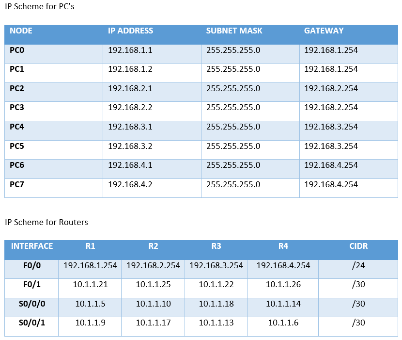
The following topology is going to be a full mesh, with LANs on each router. This will add to the complexity of the lab, so we can look at everything we have talked about. Before we begin configurations, we must know the IP addressing scheme of each device. The following table shows the addresses, gateways, and masks of each device:
The routing protocol in use must learn to use our show commands:
R1#sh ip protocols
Routing Protocol is "eigrp 100 "
Outgoing update filter list for all interfaces is not set
Incoming update filter list for all interfaces is not set
Default networks flagged in outgoing updates
Default networks accepted from incoming updates
EIGRP metric weight K1=1, K2=0, K3=1, K4=0, K5=0
EIGRP maximum hopcount 100
EIGRP maximum metric variance 1
Redistributing: eigrp 100
Automatic network summarization is not in effect
Maximum path: 4
Routing for Networks:
192.168.1.0
10.0.0.0
Routing Information Sources:
Gateway Distance Last Update
10.1.1.10 90 1739292
10.1.1.22 90 1755881
10.1.1.6 90 1774985
Distance: internal 90 external 170
Okay, you have the topology, the IP scheme, and which routing protocol to use, and its autonomous system. As you can see, I already configured the lab, but now it's your turn.
You are going to have to configure it to follow along with the show command we are about to do.
You should, by now, know your admin commands. The first thing you need to worry about is connectivity, so I will show you the output of the sh ip int brief command from each router:
As you can see, all my interfaces have the correct IPv4 addresses and they are all up; your configuration should be the same. If you also want to see the subnet mask of the command you could have done, which is like sh ip int brief, it is sh protocols:
Unlock access to the largest independent learning library in Tech for FREE!
Get unlimited access to 7500+ expert-authored eBooks and video courses covering every tech area you can think of.
Renews at $19.99/month. Cancel anytime
After you have checked that all your interfaces are up and running, it is now time to configure the routing protocol. We will be doing a single autonomous system using the number 100 on all the routers, so they can share the same routing table. Through the uses of hello messages, they can discover their neighbors. The configuration of the EIGRP protocol should look like this per router:
As you can see, we are using the 100 autonomous system number for all routers and when we advertise the networks, especially the 10.1.1.0 network, we use the classfull boundary, which is a Class A network. We must not forget the no auto-summary command or it will not send out the subnet mask on the updates.
Now, let's check out our routing tables to see if we have converged fully, meaning we have found all our networks:
R2
R2#SH IP ROUTE
Gateway of last resort is not set
10.0.0.0/30 is subnetted, 6 subnets
D 10.1.1.4 [90/2172416] via 10.1.1.26, 02:27:38, FastEthernet0/1
C 10.1.1.8 is directly connected, Serial0/0/0
D 10.1.1.12 [90/2172416] via 10.1.1.26, 02:27:38, FastEthernet0/1
C 10.1.1.16 is directly connected, Serial0/0/1
D 10.1.1.20 [90/2172416] via 10.1.1.9, 02:27:39, Serial0/0/0[90/2172416] via 10.1.1.18, 02:27:39, Serial0/0/1
C 10.1.1.24 is directly connected, FastEthernet0/1
D 192.168.1.0/24 [90/2172416] via 10.1.1.9, 02:27:39, Serial0/0/0
C 192.168.2.0/24 is directly connected, FastEthernet0/0
D 192.168.3.0/24 [90/2172416] via 10.1.1.18, 02:27:39, Serial0/0/1
D 192.168.4.0/24 [90/30720] via 10.1.1.26, 02:27:38, FastEthernet0/1
R3
R3Gateway of last resort is not set
10.0.0.0/30 is subnetted, 6 subnets
D 10.1.1.4 [90/2172416] via 10.1.1.21, 02:28:49, FastEthernet0/1
D 10.1.1.8 [90/2172416] via 10.1.1.21, 02:28:49, FastEthernet0/1
C 10.1.1.12 is directly connected, Serial0/0/1
C 10.1.1.16 is directly connected, Serial0/0/0
C 10.1.1.20 is directly connected, FastEthernet0/1
D 10.1.1.24 [90/2172416] via 10.1.1.17, 02:28:50, Serial0/0/0[90/2172416] via 10.1.1.14, 02:28:50, Serial0/0/1
D 192.168.1.0/24 [90/30720] via 10.1.1.21, 02:28:49, FastEthernet0/1
D 192.168.2.0/24 [90/2172416] via 10.1.1.17, 02:28:50, Serial0/0/0
C 192.168.3.0/24 is directly connected, FastEthernet0/0
D 192.168.4.0/24 [90/2172416] via 10.1.1.14, 02:28:50, Serial0/0/1
R4
R4#SH IP ROUTE
Gateway of last resort is not set
10.0.0.0/30 is subnetted, 6 subnets
C 10.1.1.4 is directly connected, Serial0/0/1
D 10.1.1.8 [90/2172416] via 10.1.1.25, 02:29:51, FastEthernet0/1
C 10.1.1.12 is directly connected, Serial0/0/0
D 10.1.1.16 [90/2172416] via 10.1.1.25, 02:29:51, FastEthernet0/1
D 10.1.1.20 [90/2172416] via 10.1.1.5, 02:29:52, Serial0/0/1[90/2172416] via 10.1.1.13, 02:29:52, Serial0/0/0
C 10.1.1.24 is directly connected, FastEthernet0/1
D 192.168.1.0/24 [90/2172416] via 10.1.1.5, 02:29:52, Serial0/0/1
D 192.168.2.0/24 [90/30720] via 10.1.1.25, 02:29:51, FastEthernet0/1
D 192.168.3.0/24 [90/2172416] via 10.1.1.13, 02:29:52, Serial0/0/0
C 192.168.4.0/24 is directly connected, FastEthernet0/0
It seems that EIGRP has found all our different networks and has applied the best metric to each destination. If you look closely at the routing table, you will see that two networks have multiple paths to it: 10.1.1.20 and 10.1.1.24. The path that it takes is determined by the router that is learning it.
So, what does that mean? EIGRP has two successor routes or two feasible distances that are equal, so they must go to the routing table. All other routes to include the successor routes will be in the topology table.
I have highlighted the networks that have the multiple paths, which means they can go in either direction, but EIGRP will load balance by default when it has multiple paths:
We need to see exactly which path it is taking to this network: 10.1.1.20. This is from the R4 viewpoint. It could go via 10.1.1.5 or 10.1.1.13, so let's use the tools we have at hand, such as traceroute:
R4#traceroute 10.1.1.20Type escape sequence to abort.Tracing the route to 10.1.1.201 10.1.1.5 7msec 1 msec 6 msec
So, even if they have the identical metric of 2172416, it will choose the first path from top to bottom, to send the packet to the destination. If that path is shut down or is disconnected, it will still have an alternate route to get to the destination.
In your lab, if you followed the configuration exactly as I did it, you should get the same results. But, this is where your curiosity should come in. Shut down the 10.1.1.5 interface and see what happens. What will your routing table look like then? Will it have only one route to the destination or will it have more than one? Remember that when a successor route goes down, EIGRP will query the topology table to find an alternate route, but in this situation, will it do that, since an alternate route exists?
Let's take a look:
R1(config)#int s0/0/0R1(config-if)#shut
Now let's take a look at the routing table from the R4 perspective.
The first thing that happens is the following:
R4#
%LINK-5-CHANGED: Interface Serial0/0/1, changed state to down
%LINEPROTO-5-UPDOWN: Line protocol on Interface Serial0/0/1, changed state to down
%DUAL-5-NBRCHANGE: IP-EIGRP 100: Neighbor 10.1.1.5 (Serial0/0/1) is down: interface down
R4#sh ip route
Gateway of last resort is not set
10.0.0.0/30 is subnetted, 5 subnets
D 10.1.1.8 [90/2172416] via 10.1.1.25, 02:57:14, FastEthernet0/1
C 10.1.1.12 is directly connected, Serial0/0/0
D 10.1.1.16 [90/2172416] via 10.1.1.25, 02:57:14, FastEthernet0/1
D 10.1.1.20 [90/2172416] via 10.1.1.13, 02:57:15, Serial0/0/0
C 10.1.1.24 is directly connected, FastEthernet0/1
D 192.168.1.0/24 [90/2174976] via 10.1.1.13, 02:57:14, Serial0/0/0
D 192.168.2.0/24 [90/30720] via 10.1.1.25, 02:57:14, FastEthernet0/1
D 192.168.3.0/24 [90/2172416] via 10.1.1.13, 02:57:15, Serial0/0/0
C 192.168.4.0/24 is directly connected, FastEthernet0/0
Only one route exists, which is 10.1.1.13. It had the same metric as 10.1.1.5. So, in this situation, there was no need to query the topology table, since an existing alternate route already existed in the routing table. But, let's verify this with the traceroute command:
R4#traceroute 10.1.1.20
Type escape sequence to abort.
Tracing the route to 10.1.1.20
1 10.1.1.13 0 msec 5 msec 1 msec (alternate path)
1 10.1.1.5 7msec 1 msec 6 msec (original path)
Since it only had one path to get to the 10.1.1.20 network, it was quicker in getting there, but when it had multiple paths, it took longer. Now I know we are talking about milliseconds, but still, it is a delay, none the less.
So, what does this tell us? Redundancy is not always a good thing. This is a full-mesh topology, which is very costly and we are running into delays. So, be careful in your design of the network. There is such a thing as too much redundancy and you can easily create Layer 3 loops and delays.
We looked at the routing table, but not the topology table, so I am going to turn on the s0/0/0 interface again and look at the routing table once more to make sure all is as it was and then look at the topology table.
Almost immediately after turning on the s0/0/0 interface on R1, I receive the following message:
R4#
%LINK-5-CHANGED: Interface Serial0/0/1, changed state to up
%LINEPROTO-5-UPDOWN: Line protocol on Interface Serial0/0/1, changed state to up
%DUAL-5-NBRCHANGE: IP-EIGRP 100: Neighbor 10.1.1.5 (Serial0/0/1) is up: new adjacency
Let us peek at the routing table on R4:
R4#sh ip route
Gateway of last resort is not set
10.0.0.0/30 is subnetted, 6 subnets
C 10.1.1.4 is directly connected, Serial0/0/1
D 10.1.1.8 [90/2172416] via 10.1.1.25, 03:08:05, FastEthernet0/1
C 10.1.1.12 is directly connected, Serial0/0/0
D 10.1.1.16 [90/2172416] via 10.1.1.25, 03:08:05, FastEthernet0/1
D 10.1.1.20 [90/2172416] via 10.1.1.13, 03:08:05, Serial0/0/0 [90/2172416] via 10.1.1.5, 00:01:45, Serial0/0/1
C 10.1.1.24 is directly connected, FastEthernet0/1
D 192.168.1.0/24 [90/2172416] via 10.1.1.5, 00:01:45, Serial0/0/1
D 192.168.2.0/24 [90/30720] via 10.1.1.25, 03:08:05, FastEthernet0/1
D 192.168.3.0/24 [90/2172416] via 10.1.1.13, 03:08:05, Serial0/0/0
C 192.168.4.0/24 is directly connected, FastEthernet0/0
Notice that the first path in the network is through 10.1.1.13 and not 10.1.1.5, as before.
Now let us look at the topology table:
Keep in mind that the topology has all possible routes to all destination networks. Only the ones with the lowest FD make it to the routing table and earn the title of the successor route. If you notice the highlighted networks, they are the same as the ones on the routing table. They both have the exact same metric, so they would both earn the title of successor route.
But let's analyze another network. Let's choose that last one on the list, 192.168.3.0. It has multiple routes, but the metrics are not the same. If you notice, the FD is 2172416, so 10.1.1.13 would be the successor route, but 10.1.1.5 has a metric of 2174976, which truly makes it a feasible successor and will remain in the topology table.
So, what does that mean to us? Well, if the successor route was to go down, then it would have to query the topology table in order to acquire an alternate path. What does the routing table show us about the 192.168.3.0 network, from the R3 perspective?
R4#sh ip routeD 192.168.3.0/24 [90/2172416] via 10.1.1.13, 03:28:10, Serial0/0/0
There is only one route, the one with the lowest FD, so it's true that, in this case, if this route goes down, a query to the topology table must take place.
So, you see it all depends on how you set up your network topology; you may have a feasible successor, or you may not. So, you must analyze the network you are working with to make it an effective network.
We have not even changed the bandwidth of any of the interfaces or used the variance command in order to include other routes in our load balancing.
Thus, in this article, we covered, how EIGRP works, its features, and configuring EIGRP for single autonomous systems and multiple autonomous systems.

 United States
 Great Britain
 India
India
 Germany
 France
 Canada
 Russia
 Spain
Spain
 Brazil
 Australia
 Singapore
 Canary Islands
 Hungary
 Ukraine
 Luxembourg
 Estonia
 Lithuania
 South Korea
 Turkey
 Switzerland
 Colombia
 Taiwan
 Chile
Chile
 Norway
 Ecuador
 Indonesia
 New Zealand
 Cyprus
 Denmark
 Finland
 Poland
 Malta
Malta
 Czechia
 Austria
 Sweden
 Italy
Italy
 Egypt
Egypt
 Belgium
 Portugal
 Slovenia
 Ireland
 Romania
 Greece
 Argentina
 Netherlands
 Bulgaria
 Latvia
 South Africa
 Malaysia
 Japan
Japan
 Slovakia
 Philippines
 Mexico
 Thailand