In this first of several articles Bill Pretty, author of Getting Started with Electronic Projects and Building a Home Security System with BeagleBone, shows us how to use a Zigbee point-to-point network to create our very own remote controlled RC car!
What Network are we using?
In the final chapter of Getting Started with Electronics Projects, I introduced you to the concept of ZigBee RF transmitters and receivers. We used the Type 1 version of XBee devices, because they were capable of “pin mirroring”. In simple terms, this means that whatever change occurs on the I/O pin of the transmitting device is reflected on the corresponding output pin of the receiving XBee device. This feature allows us to use the receiver XBees in a stand-alone configuration, like we did with the alarm system. The type 1 XBee network is configured as a “Star” network. That means that there is only one ‘master’ and in our case, only one end device.
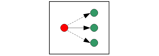
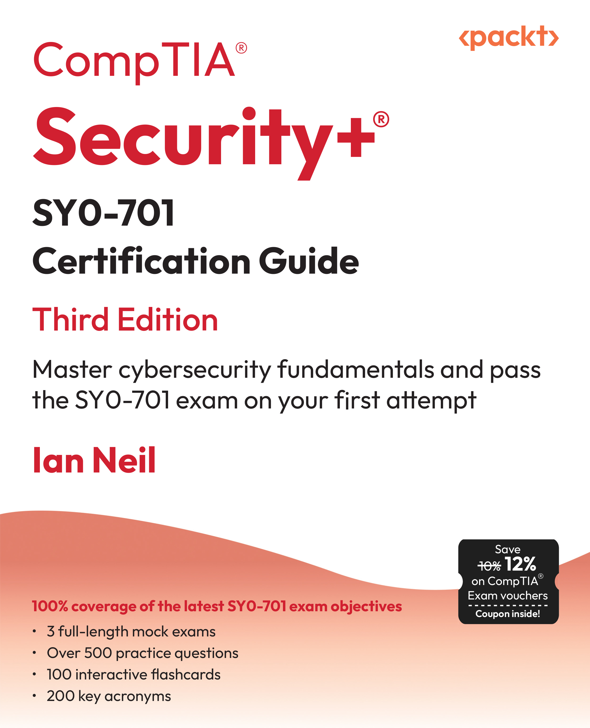
Figure 1 Star Network
In the figure above, the controlling XBee is shown in red, while the end device(s) are shown in green.
The RC cars that we are going to be using in this article have three ‘basic’ types of steering control. I will refer to them as ‘toy’ cars to differentiate them from higher end ‘model’ cars which tend to come out of the box with servo control and microprocessor control. We will be using toy cars that I got from the local thrift store for less than ten dollars, because the remote control was missing! While the remote would come in handy, it isn’t really necessary, because we will be replacing both ends of the system.
The first kind of steering system is the simplest and the cheapest to manufacture. A command from the controller tells the front wheels to turn left or right and the wheels will continue to try and turn in the proper direction as long as they are receiving the command, even though the steering motor has hit the limit of the travel. This type of steering may have a series resistor to prevent the motor from burning out, or it may just rely on the limited current capacity of the battery. When the user centres the control, the motor is turned off and an extension spring returns the wheels to the centre position. This makes our control job really easy. We need four signals/commands; forward, reverse, left and right. The spring does the rest.
The second type of steering circuit is a simple single pole, double throw switch; which is connected to the motor. The switch changes position when the motor reaches either the full left or full right position. There is no indication of ‘centre’, so this type of steering still relies on a spring for auto-centring.
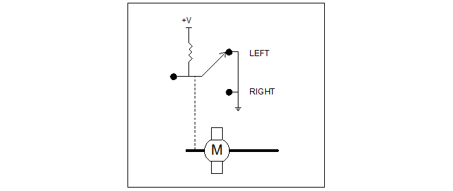
Figure 2 Switch Feedback
The third and most complicated type of steering control tends to be seen in toys with rechargeable batteries, like NiCad or NiMH as well. These types of batteries provide more power than alkaline ‘flash light’ batteries. For that reason a slightly more complex steering system is required. This type of system uses an “analog feedback” servo system. What it is is a standard DC motor connected to a potentiometer; so that when the motor turns so does the pot. The wiper of the pot provides a DC voltage that is proportional to the position of the motor.
Figure 3 Analog Feedback Servo
The steering control circuit will receive three voltages that we are concerned about; full left, full right and centre. This type of servo requires a comparator circuit or a small microprocessor to detect the three positions. More on comparator circuits in future articles.
The following circuit will work with the first two types of steering circuits. The circuit diagrams are shown below.
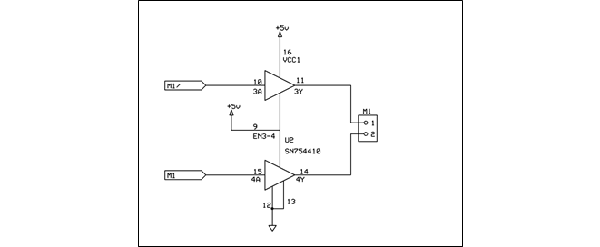
Figure 4
In the circuit above, U2 is half of an SN754410 H-Bridge controller integrated circuit. In order for the motor to move the ‘M1’ and ‘M1/’ signals must be at a different level. A logic 0 on M1/ and a logic 1 on M1 will make the motor turn in one direction and a logic 1 on M1/ and a logic 0 on M1 will make it turn in the opposite direction. While either two logic 1’s or 0’s will cause the motor to stop moving. In this way we have either left/right/centre or forward/reverse/stop control.
Unlock access to the largest independent learning library in Tech for FREE!
Get unlimited access to 7500+ expert-authored eBooks and video courses covering every tech area you can think of.
Renews at $19.99/month. Cancel anytime
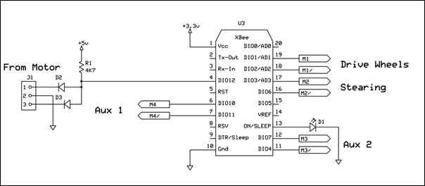
Figure 5
Figure 5 above, shows the connections to the XBee receiver module. As I said earlier, when an I/O pin on the controller goes low, the corresponding pin on the receiver “mirrors” that input. The outputs M1, M1/, M2 and M2/ are connected to the drive and steering motors. The SN754410 is capable of sourcing or sinking about 1 amp, so AUX-1 and AUX-2 can be used to drive LED’s or other devices.
The controller circuit is shown below. The circuit is actually taken from a sample circuit I found on the XBee vendor site: http://examples.digi.com/sensors/joystick-with-xbee/
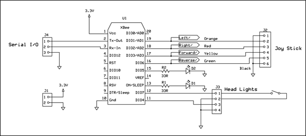
Figure 6 XBee Transmitter
The colours represent the wires which come from the joystick. In this case it is a simple arcade style joystick, which uses four micro switches rather than potentiometers. So when the joystick is moved, one or more inputs to the XBee transmitter are grounded (Logic 0) and this information is sent to the receiver in the car. The joystick, available from Adafruit http://examples.digi.com/sensors/joystick-with-xbee/ is shown below.

Figure 7 Adafruit Joystick
The AUX-1 input is connected to a simple toggle switch, which in this case is used to control the vehicle’s headlights. This is a very simple controller which is designed to control the first two types of vehicles. A more complex design is required to control more complex vehicles. A single board computer such as an Arduino, RaspberryPi or Beaglebone would be required, so that we can read inputs from the joystick as well as digital and analog inputs sent to it from the vehicle.
Summary
So that’s it for this blog, I hope you enjoyed reading it. In future editions of this topic, I’ll show you how to configure the XBee modules using the Windows application. This method is a lot easier that the one presented in the example on the Digi site.
About the Author
Bill began his career in electronics in the early 80’s with a small telecom startup company that would eventually become a large multinational. He left there to pursue a career in commercial aviation in Canada’s north. From there he joined the Ontario Center for Microelectronics, a provincially funded research and development center. Bill left there for a career in the military as a civilian contractor at what was then called Defense Research Establishment Ottawa. That began a career which was to span the next 25 years, and continues today.
Over the years Bill has acquired extensive knowledge in the field of technical security and started his own company in 2010. That company is called William Pretty Security Inc. and provides support in the form of research and development, to various law enforcement and private security agencies.
Bill has published and presented a number of white papers on the subject of technical security. Bill was also a guest presenter for a number of years at the Western Canada Technical Conference, a law enforcement only conference held every year in western Canada. A selection of these papers is available for download from his web site.
www.williamprettysecurity.com
If you’re interested in building more of your own projects, then be sure to check out Bill’s titles available now in both print and eBook format! If you’re new to working with microcontrollers be sure to pick up Getting Started with Electronic Projects to start creating a whole host of great projects you can do in a single weekend with LM555, ZigBee, and BeagleBone components! If you’re looking for something more advanced to tinker with, then Bill’s other title - Building a Home Security System with BeagleBone – is perfect for hobbyists looking to make a bigger project!

 United States
 Great Britain
 India
India
 Germany
 France
 Canada
 Russia
 Spain
Spain
 Brazil
 Australia
 Singapore
 Canary Islands
 Hungary
 Ukraine
 Luxembourg
 Estonia
 Lithuania
 South Korea
 Turkey
 Switzerland
 Colombia
 Taiwan
 Chile
Chile
 Norway
 Ecuador
 Indonesia
 New Zealand
 Cyprus
 Denmark
 Finland
 Poland
 Malta
Malta
 Czechia
 Austria
 Sweden
 Italy
Italy
 Egypt
Egypt
 Belgium
 Portugal
 Slovenia
 Ireland
 Romania
 Greece
 Argentina
 Netherlands
 Bulgaria
 Latvia
 South Africa
 Malaysia
 Japan
Japan
 Slovakia
 Philippines
 Mexico
 Thailand