


A polygon is an n-sided object composed of vertices (points), edges, and faces. A face can face in or out or be double-sided. For most real-time VR, we use single–sided polygons; we noticed this when we first placed a plane in the world, depending on the orientation, you may not see it. In today’s tutorial, we will understand why Polygons are the best way to present real-time graphics.
To really show how this all works, I’m going to show the internal format of an OBJ file. Normally, you won’t hand edit these — we are beyond the days of VR constructed with a few thousand polygons (my first VR world had a train that represented downloads, and it had six polygons, each point lovingly crafted by hand), so hand editing things isn’t necessary, but you may need to edit the OBJ files to include the proper paths or make changes your modeler may not do natively–so let’s dive in!
This article is an excerpt from a book written by John Gwinner titled Getting Started with React VR. In this book, you’ll gain a deeper understanding of Virtual Reality and a full-fledged VR app to add to your profile.
Polygons are constructed by creating points in 3D space, and connecting them with faces. You can consider that vertices are connected by lines (most modelers work this way), but in the native WebGL that React VR is based on, it’s really just faces. The points don’t really exist by themselves, but more or less “anchor” the corners of the polygon.
For example, here is a simple triangle, modeled in Blender:

In this case, I have constructed a triangle with three vertices and one face (with just a flat color, in this case green). The edges, shown in yellow or lighter shade, are there for the convenience of the modeler and won’t be explicitly rendered.
Here is what the triangle looks like inside our gallery:
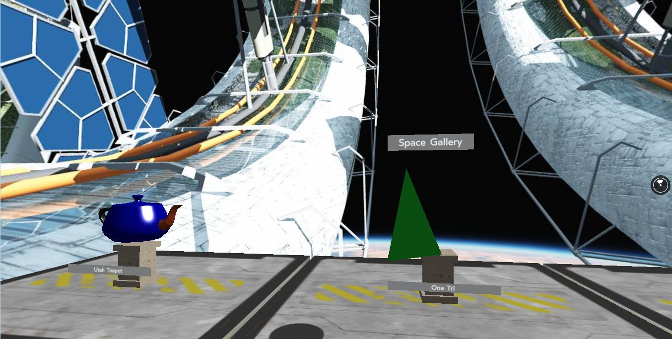
If you look closely in the Blender photograph, you’ll notice that the object is not centered in the world. When it exports, it will export with the translations that you have applied in Blender. This is why the triangle is slightly off center on the pedestal. The good news is that we are in outer space, floating in orbit, and therefore do not have to worry about gravity. (React VR does not have a physics engine, although it is straightforward to add one.)
The second thing you may notice is that the yellow lines (lighter gray lines in print) around the triangle in Blender do not persist in the VR world. This is because the file is exported as one face, which connects three vertices.
The plural of vertex is vertices, not vertexes. If someone asks you about vertexes, you can laugh at them almost as much as when someone pronouncing Bézier curve as “bez ee er.”
Ok, to be fair, I did that once, now I always say Beh zee a.
Okay, all levity aside, now let’s make it look more interesting than a flat green triangle. This is done through something usually called as texture mapping.
Honestly, the phrase “textures” and “materials” often get swapped around interchangeably, although lately they have sort of settled down to materials meaning anything about an object’s physical appearance except its shape; a material could be how shiny it is, how transparent it is, and so on. A texture is usually just the colors of the object — tile is red, skin may have freckles — and is therefore usually called a texture map which is represented with a JPG, TGA, or other image format.
There is no real cross software file format for materials or shaders (which are usually computer code that represents the material). When it comes time to render, there are some shader languages that are standard, although these are not always used in CAD programs.
You will need to learn what your CAD program uses, and become proficient in how it handles materials (and texture maps). This is far beyond the scope of this book.
The OBJ file format (which is what React VR usually uses) allows the use of several different texture maps to properly construct the material. It also can indicate the material itself via parameters coded in the file. First, let’s take a look at what the triangle consists of. We imported OBJ files via the Model keyword:
<Model
    source={{
        obj: asset('OneTri.obj'),
        mtl: asset('OneTri.mtl'),
        }}
    style={{
            transform: [
                { translate: [ -0, -1, -5. ] },
                { scale: .1 },
            ]
        }}
/>
First, let’s open the MTL (material) file (as the .obj file uses the .mtl file). The OBJ file format was developed by Wavefront:
# Blender MTL File: 'OneTri.blend'
# Material Count: 1
newmtl BaseMat
Ns 96.078431
Ka 1.000000 1.000000 1.000000
Kd 0.040445 0.300599 0.066583
Ks 0.500000 0.500000 0.500000
Ke 0.000000 0.000000 0.000000
Ni 1.000000
d 1.000000
illum 2
A lot of this is housekeeping, but the important things are the following parameters:
- Ka : Ambient color, in RGB format
- Kd : Diffuse color, in RGB format
- Ks : Specular color, in RGB format
- Ns : Specular exponent, from 0 to 1,000
- d : Transparency (d meant dissolved). Note that WebGL cannot normally show refractive materials, or display real volumetric materials and raytracing, so d is simply the percentage of how much light is blocked. 1 (the default) is fully opaque. Note that d in the .obj specification works for illum mode 2.
- Tr : Alternate representation of transparency; 0 is fully opaque.
- illum <#> (a number from 0 to 10). Not all illumination models are supported by WebGL. The current list is:
- Color on and Ambient off.
- Color on and Ambient on.
- Highlight on (and colors) <= this is the normal setting.
- There are other illumination modes, but are currently not used by WebGL. This of course, could change.
- Ni is optical density. This is important for CAD systems, but the chances of it being supported in VR without a lot of tricks are pretty low. Computers and video cards get faster and faster all the time though, so maybe optical density and real time raytracing will be supported in VR eventually, thanks to Moore’s law (statistically, computing power roughly doubles every two years or so).
Very important:
Make sure you include the “lit” keyword with all of your model declarations, otherwise the loader will assume you have only an emissive (glowing) object and will ignore most of the parameters in the material file!
YOU HAVE BEEN WARNED. It’ll look very weird and you’ll be completely confused. Don’t ask me why I know!
The OBJ file itself has a description of the geometry. These are not usually something you can hand edit, but it’s useful to see the overall structure. For the simple object, shown before, it’s quite manageable:
# Blender v2.79 (sub 0) OBJ File: 'OneTri.blend'
# www.blender.org
mtllib OneTri.mtl
o Triangle
v -7.615456 0.218278 -1.874056
v -4.384528 15.177612 -6.276536
v 4.801097 2.745610 3.762014
vn -0.445200 0.339900 0.828400
usemtl BaseMat
s off
f 3//1 2//1 1//1
First, you see a comment (marked with #) that tells you what software made it, and the name of the original file. This can vary. The mtllib is a call out to a particular material file, that we already looked at. The o lines (and g line is if there a group) define the name of the object and group; although React VR doesn’t really use these (currently), in most modeling packages this will be listed in the hierarchy of objects. The v and vn keywords are where it gets interesting, although these are still not something visible. The v keyword creates a vertex in x, y, z space. The vertices built will later be connected into polygons. The vn establishes the normal for those objects, and vt will create the texture coordinates of the same points. More on texture coordinates in a bit.
The usemtl BaseMat establishes what material, specified in your .mtl file, that will be used for the following faces.
The s off means smoothing is turned off. Smoothing and vertex normals can make objects look smooth, even if they are made with very few polygons. For example, take a look at these two teapots; the first is without smoothing.

Looks pretty computer graphics like, right? Now, have a look at the same teapot with the “s 1” parameter specified throughout, and normals included in the file. This is pretty normal (pun intended), what I mean is most CAD software will compute normals for you. You can make normals; smooth, sharp, and add edges where needed. This adds detail without excess polygons and is fast to render.
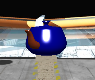
The smooth teapot looks much more real, right? Well, we haven’t seen anything yet! Let’s discuss texture.
I didn’t used to like Sushi because of the texture. We’re not talking about that kind of texture.
Texture mapping is a lot like taking a piece of Christmas wrapping paper and putting it around an odd shaped object. Just like when you get that weird looking present at Christmas and don’t know quite what to do, sometimes doing the wrapping doesn’t have a clear right way to do it. Boxes are easy, but most interesting objects aren’t always a box. I found this picture online with the caption “I hope it’s an X-Box.“

The “wrapping” is done via U, V coordinates in the CAD system. Let’s take a look at a triangle, with proper UV coordinates. We then go get our wrapping paper, that is to say, we take an image file we are going to use as the texture, like this:

We then wrap that in our CAD program by specifying this as a texture map. We’ll then export the triangle, and put it in our world.

You would probably have expected to see “left and bottom” on the texture map. Taking a closer look in our modeling package (Blender still) we see that the default UV mapping (using Blender’s standard tools) tries to use as much of the texture map as possible, but from an artistic standpoint, may not be what we want.

This is not to show that Blender is “yer doin’ it wrong” but to make the point that you’ve got to check the texture mapping before you export. Also, if you are attempting to import objects without U,V coordinates, double-check them!
If you are hand editing an .mtl file, and your textures are not showing up, double–check your .obj file and make sure you have vt lines; if you don’t, the texture will not show up. This means the U,V coordinates for the texture mapping were not set.
Texture mapping is non-trivial; there is quite an art about it and even entire books written about texturing and lighting. After having said that, you can get pretty far with Blender and any OBJ file if you’ve downloaded something from the internet and want to make it look a little better. We’ll show you how to fix it. The end goal is to get a UV map that is more usable and efficient. Not all OBJ file exporters export proper texture maps, and frequently .obj files you may find online may or may not have UVs set.
You can use Blender to fix the unwrapping of your model. We have several good Blender books to provide you a head start in it. You can also use your favorite CAD modeling program, such as Max, Maya, Lightwave, Houdini, and so on.
This is important, so I’ll mention it again in an info box. If you already use a different polygon modeler or CAD page, you don’t have to learn Blender; your program will undoubtedly work fine. You can skim this section.
If you don’t want to learn Blender anyway, you can download all of the files that we construct from the Github link. You’ll need some of the image files if you do work through the examples. Files for this article are at: http://bit.ly/VR_Chap7.
To summarize, we learned the basics of polygon modeling with Blender, also got to know the importance of polygon budgets, how to export those models, and details about the OBJ/MTL file formats.
To know more about how to make virtual worlds look real, do check out this book Getting Started with React VR.