


In this article, we will look at how to build an actuator application for controlling illuminations.
This article is an excerpt from the book, Mastering Internet of Things, written by Peter Waher. This book will help you design and implement IoT solutions with single board computers.
Preparing our project
Let’s create a new Universal Windows Platform application project. This time, we’ll call it Actuator. We can also use the Raspberry Pi 3, even though we will only use the relay in this project.
To make the persistence of application states even easier, we’ll also include the latest version of the NuGet package Waher.Runtime.Settings in the project. It uses the underlying object database defined by Waher.Persistence to persist application settings.
Defining control parameters
Actuators come in all sorts, types, and sizes, from the very complex to the very simple. While it would be possible to create a proprietary format that configures the actuator in a bulk operation, such a method is doomed to fail if you aim for any type of interoperable communication. Since the internet is based on interoperability as a core principle, we should consider this from the start, during the design phase.
Interoperability means devices can learn to operate together, even if they are from different manufacturers. To achieve this, devices must be able to describe what they can do, in a way that each participant understands. To be able to do this, we need a way to break down (divide and conquer) a complex actuator into parts that are easily described and understood. One way is to see an actuator as a collection of control parameters. Each control parameter is a named parameter with a simple and recognizable data type. (In the same way, we can see a sensor as a collection of sensor data fields.):
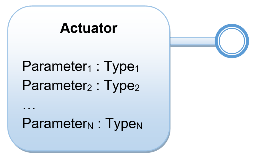
For our example, we will only need one control parameter: A Boolean control parameter controlling the state of our relay. We’ll just call it Output, for simplicity.
Understanding relays
Relays, simply put, are electric switches that we can control using a small output signal. They’re perfect for small controllers, like Raspberry Pi, to switch other circuits with higher voltages on and off. The simplest example is to use a relay to switch a lamp on and off. We can’t light the lamp using the voltage available to us in Raspberry Pi, but we can use a relay as a switch to control the lamp.
The principal part of a normal relay is a coil. When electricity runs through it, it magnetizes an iron core, which in turn moves a lever from the Normally Closed (NC) connector to the Normally Open (NO) connector. When electricity is cut, a spring returns the lever from the NO connector to the NC connector. This movement of the lever from one connector to the other causes a characteristic clicking sound. This tells you that the relay works. The lever in turn is connected to the Common Ground (COM) connector.
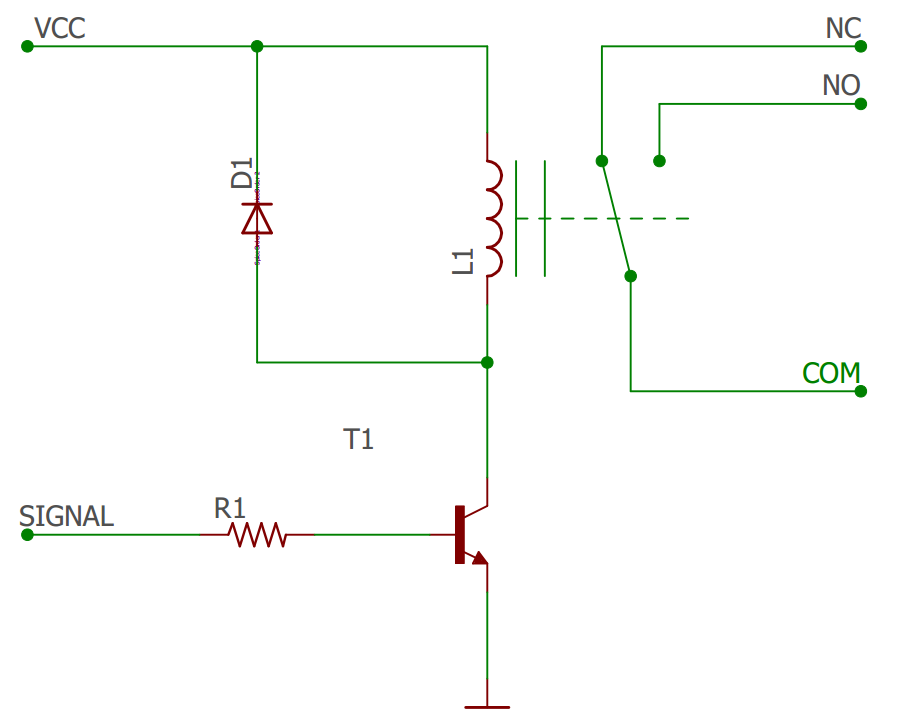
The following figure illustrates how a simple relay is constructed. We control the flow of the current through the coil (L1) using our output SIGNAL (D1 in our case). Internally, in the relay, a resistor (R1) is placed before the base pin of the transistor (T1), to adapt the signal voltage to an appropriate level. When we connect or cut the current through the coil, it will induce a reverse current. This may be harmful for the transistor when the current is being cut. For that reason, a fly-back diode (D1) is added, allowing excess current to be fed back, avoiding harm to the transistor:
Connecting our lamp
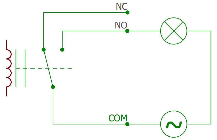
Now that we know how a relay works, it’s relatively easy to connect our lamp to it. Since we want the lamp to be illuminated when we turn the relay on (set D1to HIGH), we will use the NO and COM connectors, and let the NC connector be. If the lamp has a normal two-wire AC cable, we can insert the relay into the AC circuit by simply cutting one of the wires, inserting one end into the NO connector and the other into the COM connector, as is illustrated in the following figure:
Connecting an LED
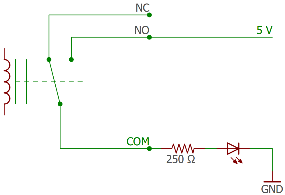
An alternative to working with the alternating current (AC) is to use a low-power direct current (DC) source and an LED to simulate a lamp. You can connect the COM connector to a resistor and an LED, and then to ground (GND) on one end, and the NO directly to the 5V or 3.3V source on the Raspberry Pi on the other end. The size of the resistor is determined by how much current the LED needs to light up, and the voltage source you choose. If the LED needs 20 mA, and you connect it to a 5V source, Ohms Law tells us we need an R = U/I = 5V/0.02A = 250 Ω resistor. The following figure illustrates this:
Controlling the output
The relay is connected to our digital output pin 9 on the Arduino board. As such, controlling it is a simple call to the digitalWrite() method on our arduino object. Since we will need to perform this control action from various locations in code in later chapters, we’ll create a method for it:
internal async Task SetOutput(bool On, string Actor)
{
   if (this.arduino != null)
   {
         this.arduino.digitalWrite(9,
               On ? PinState.HIGH : PinState.LOW);
The first parameter simply states the new value of the control parameter. We’ll add a second parameter that describes who is making the requested change. This will come in handy later, when we allow online users to change control parameters.
Persisting control parameter states
If the device reboots for some reason, for instance after a power outage, it’s normally desirable that it returns to the state it was in before it shut down. For this, we need to persist the output value. We can use the object database defined in Waher.Persistence and Waher.Persistence.Files for this. But for simple control states, we don’t need to create our own data-bearing classes. That has already been done by Waher.Runtime.Settings. To use it, we first include the NuGet, as described earlier. We must also include its assembly when we initialize the runtime inventory, which is used by the object database:
Types.Initialize(
   typeof(FilesProvider).GetTypeInfo().Assembly,
   typeof(App).GetTypeInfo().Assembly,
   typeof(RuntimeSettings).GetTypeInfo().Assembly);
The Waher.Runtime.Inventory.Loader library, available as a NuGet package, provides the capability to loop through existing assemblies in a simple manner, but it requires support for .NET Standard 1.5. You can call its TypesLoader.Initialize() method to initialize Waher.Runtime.Inventory with all assemblies available in the runtime. It also dynamically loads all permitted assemblies available in the application folder that have not been loaded.
Saving the current control state is then simply a matter of calling the Set() or SetAsync() methods on the static RuntimeSettings class, defined in the Waher.Runtime.Settings namespace:
await RuntimeSettings.SetAsync("Actuator.Output", On);
During the initialization of the device, we then call the Get() or GetAsync() methods to get the last value, if it exists. If it does not exist, a default value we define is returned:
bool LastOn = await RuntimeSettings.GetAsync("Actuator.Output",
   false);
this.arduino.digitalWrite(1, LastOn ? PinState.HIGH :
   PinState.LOW);
Logging important control events
In distributed IoT control applications, it’s vitally important to make sure unauthorized access to the system is avoided. While we will dive deeper into this subject in later chapters, one important tool we can start using it to log everything of a security interest in the event log. We can decide what to do with the event log later, whether we want to analyze or store it locally or distribute it in the network for analysis somewhere else. But unless we start logging events of security interest directly when we develop, we risk forgetting logging certain events later. So, let’s log an event every time the output is set:
Log.Informational("Setting Control Parameter.",
   string.Empty, Actor ?? "Windows user",
   new KeyValuePair<string, object>("Output", On));
If the Actor parameter is null, we assume the control parameter has been set from the Windows GUI. We use this fact, to update the window if the change has been requested from somewhere else:
if (Actor != null)
   await MainPage.Instance.OutputSet(On);
Using Raspberry Pi GPIO pins directly
The Raspberry Pi can also perform input and output without an Arduino board. But the General-Purpose Input/Output (GPIO) pins available only supports digital input and output. Since the relay module is controlled through a digital output, we can connect it directly to the Raspberry Pi, if we want. That way, we don’t need the Arduino board. (We wouldn’t be able to test-run the application on the local machine either, though.)
Checking whether GPIO is available
GPIO pins are accessed through the GpioController class defined in the Windows.Devices.Gpio namespace. First, we must check that GPIO is available on the machine. We do this by getting the default controller, and checking whether it’s available:
gpio = GpioController.GetDefault();
if (gpio != null)
{
   ...
}
else
   Log.Error("Unable to get access to GPIO pin " +
          gpioOutputPin.ToString());
Initializing the GPIO output pin
Once we have access to the controller, we can try to open exclusive access to the GPIO pin we’ve connected the relay to:
if (gpio.TryOpenPin(gpioOutputPin, GpioSharingMode.Exclusive,
   out this.gpioPin, out GpioOpenStatus Status) &&
   Status == GpioOpenStatus.PinOpened)
   {
         ...
   }
   else
         Log.Error("Unable to get access to GPIO pin " +
               gpioOutputPin.ToString());
Through the GpioPin object gpioPin, we can now control the pin. The first step is to set the operating mode for the pin. This is done by calling the SetDriveMode() method. There are many different modes a pin can be set to, not all necessarily supported by the underlying firmware and hardware. To check that a mode is supported, call the IsDriveModeSupported() method first:
if (this.gpioPin.IsDriveModeSupported(GpioPinDriveMode.Output))
{
   This.gpioPin.SetDriveMode(GpioPinDriveMode.Output);
   ...
}
else
   Log.Error("Output mode not supported for GPIO pin " +
         gpioOutputPin.ToString());
Setting the GPIO pin output
To set the actual output value, we call the Write() method on the pin object:
bool LastOn = await RuntimeSettings.GetAsync("Actuator.Output",
   false);
this.gpioPin.Write(LastOn ? GpioPinValue.High : GpioPinValue.Low);
We need to make a similar change in the SetOutput() method.
We saw how to create a simple actuator app for the Raspberry Pi using C#.
If you found our post useful, do check out this title Mastering Internet of Things, to build complex projects using motions detectors, controllers, sensors, and Raspberry Pi 3.
Read Next:
Should you go with Arduino Uno or Raspberry Pi 3 for your next IoT project?
Build your first Raspberry Pi project
Meet the Coolest Raspberry Pi Family Member: Raspberry Pi Zero W Wireless